


18
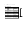
3.13 External Switches and Indicators
There are several external switches and indicators for monitoring and controlling
your CPU board. All the functions are integrated in CN2 connector.
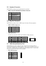
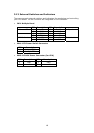
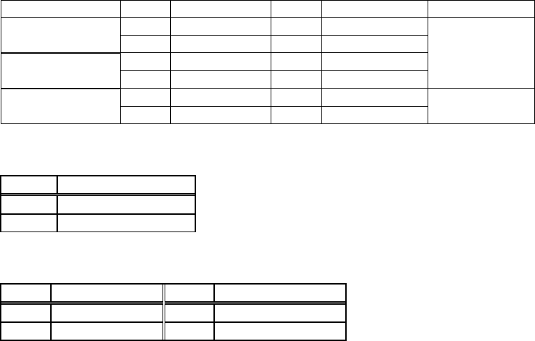
• CN2: Multiple Panel
PIN Description PIN Description
1 +5V 2 Speaker Power LED
3 GND 4 N/C
5 GND 6 N/C
7 EXTSMI# 8 +5V
Speaker
9 +5V 10 Reset Switch HDD Indicator
11 IDELED- 12 GND
Reset button
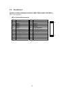
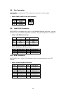
• PW1: ATX Power Switch Connector
PIN Description
1 PWR_BUTTON+
2 PWR_BUTTON-
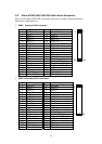
• PW2: ATX12V Power Connector (for CPU)
PIN Description PIN Description
1 GND 2 GND
3 +12V 4 +12V