


31
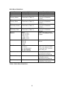
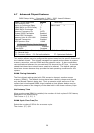
On-chip VGA
Enabled/Disabled On-chip VGA
Flash BIOS
Disabled/Enabled Flash BIOS
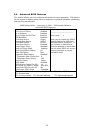
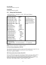
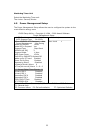
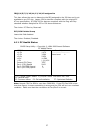
4.8 Integrated Peripherals
CMOS Setup Utility – Copyright © 1984 – 2000 Award Software
Integrated Peripherals
On-Chip Primary PCI IDE Enabled
IDE Primary Master PIO Auto
IDE Primary Slave PIO Auto
IDE Primary Master UDMA Auto
IDE Primary Slave UDMA Auto
On-Chip Secondary PCI IDE Enabled
IDE Secondary Master PIO Auto
IDE Secondary Slave PIO Auto
IDE Secondary Master UDMA Auto
IDE Secondary Slave UDMA Auto
USB Controller Enabled
USB 2.0 Controller Enabled
USB Keyboard Support Enabled
Onboard Audio Device Enabled
Init Display First PCI Slot
IDE HDD Block Mode Enabled
Power ON Function BUTTON ONLY
KB Power ON Password Enter
Hot Key Power ON Ctrl-F1
Onboard FDC Controller Enabled
Onboard Serial Port 1 3F8/IRQ4
Onboard Serial Port 2 2F8/IRQ3
UART Mode Select Normal
UR2 Duplex Mode Half
Onboard Parallel Port 378/IRQ7
Parallel Port Mode SPP
ECP Mode Use DMA 3
PWRON After PER-Fail Off
Watch Dog Timer Unit Second
Item Help
________________
Menu Level ¾
If your IDE hard drive
supports block mode select
Enabled for automatic
detection of the optimal
number of block read/write
per sector the drive can
support
↑↓←→ Move Enter: Select +/-/PU/PD: Value F10:Save ESC: Exit
F1: General Help
F5: Previous Values F6: Fail-safe defaults F7: Optimized
Defaults
Note: There are some items in bottom of scroll.
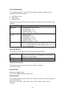
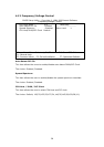
On-Chip Primary/Secondary PCI IDE
The integrated peripheral controller contains an IDE interface with support for two
IDE channels. Select Enabled to activate each channel separately.
The choice: Enabled, Disabled.
IDE Primary/Secondary Master/Slave PIO
The four IDE PIO (Programmed Input/Output) fields let users set a PIO mode (0-
4) for each of the four IDE devices supported by the onboard IDE interface.
Modes 0 through 4 provide successively increased performance. In Auto mode,
the system automatically determines the best mode for each device.
The choice: Auto, Mode 0, Mode 1, Mode 2, Mode 3, Mode 4.