


17
FOR YOUR REFERENCE
About audio (Continued)
The modulation input settings
To input the audio signal from the USB jack of the transceiver, set the modulation input connector as “USB” in the
set mode item ‘Modulation input (Data OFF)’ or ‘Modulation input (Data ON)’, or CI-V system (command).
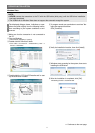
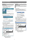
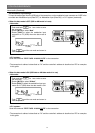
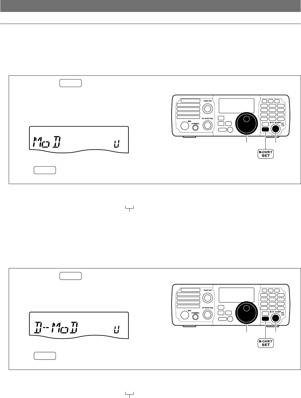
• When the data mode is OFF (SSB or AM mode is in use)
<Set mode>
q Push and hold
M-CH/RIT
SET
for 1 sec. twice to enter
the set mode.
w Rotate [M-CH] to select “Mod.”
e Rotate [DIAL] to select the modulation input
connector as “U” (USB) when the data mode is
OFF.
U (USB)
r Push
M-CH/RIT
SET
to exit the set mode and return to
normal operation.
[DIAL]
MODE
TUNER
TS
FILTER
SPCH
V/M
A/B
SPLIT
M-CL
SCAN
SET
ATT
P
.
AMP
COMP
VOX
MNF
RIT
1
2
3
4
5 6
7
8
0
50
28
1814
10
21
24
=
7
3.5
1.8
F-INP
M-CH/RIT
ENT
BAND
GENE
9
.
AGC
MW
ANF
METER
NR
NB
[M-CH]
<CI-V system>
Send the command “FE FE 76 E0 1A 03 23 03 FD”* to the transceiver.
* The transceiver’s address is described as “76” and the controller’s address is described as “E0” for examples
in this guide.
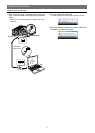
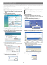
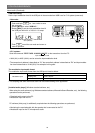
• When the data mode is ON (SSB data or AM data mode is in use)
<Set mode>
q Push and hold
M-CH/RIT
SET
for 1 sec. twice to enter
the set mode.
w Rotate [M-CH] to select “D-Mod.”
e Rotate [DIAL] to select the modulation input con-
nector as “U” (USB) when the data mode is ON.
U (USB)
r Push
M-CH/RIT
SET
to exit the set mode and return to
normal operation.
[DIAL]
MODE
TUNER
TS
FILTER
SPCH
V/M
A/B
SPLIT
M-CL
SCAN
SET
ATT
P
.
AMP
COMP
VOX
MNF
RIT
1
2
3
4
5 6
7
8
0
50
28
1814
10
21
24
=
7
3.5
1.8
F-INP
M-CH/RIT
ENT
BAND
GENE
9
.
AGC
MW
ANF
METER
NR
NB
[M-CH]
<CI-V system>
Send the command “FE FE 76 E0 1A 03 24 03 FD”* to the transceiver.
* The transceiver’s address is described as “76” and the controller’s address is described as “E0” for examples
in this guide.
USB
USB