LXD9785 PQFP Demo Board with FPGA for SS-SMII (Fiber)-to-MII Conversion
10 Development Kit Manual
Document #: 249323
Revision #: 003
Rev. Date: January 24, 2002
2.4 Typical Setup
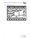
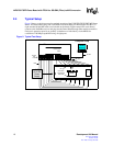
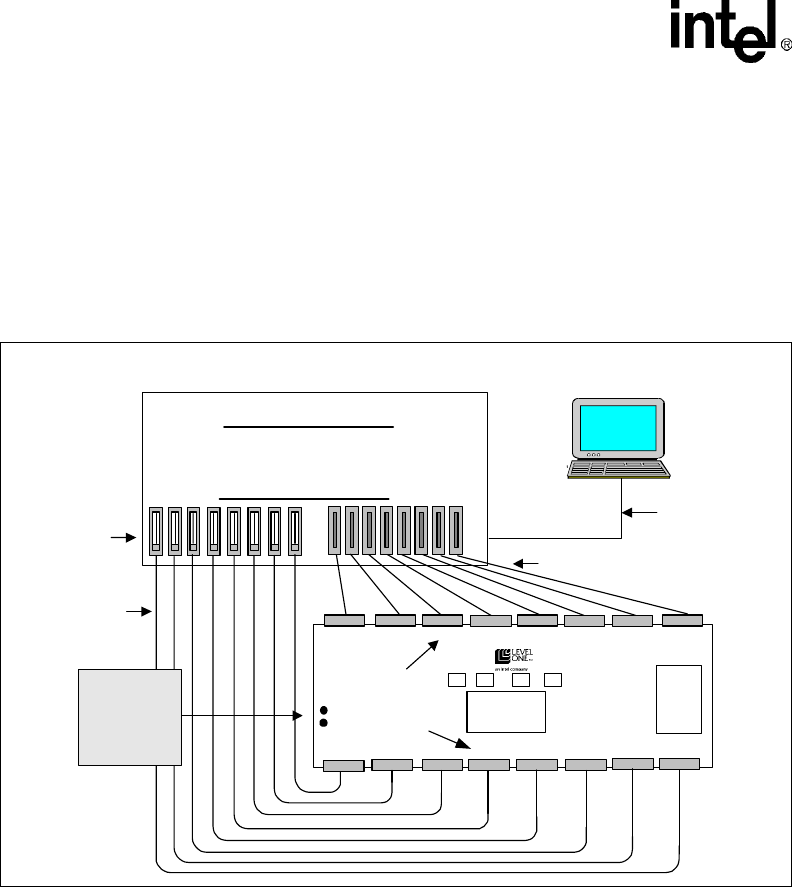
Figure 2 shows a typical test setup for standard operation of the LXD9785/9785E PQFP MII Demo
Board. The Demo Board plugs into a SmartBits Advanced Multi-port Performance Test Box via
eight standard 40-pin MII cables (not included on the board). Eight external NIC cards directly
connect to the SmartBits test box and plug into the Demo Board through fiber-module connectors.
Each port’s operation speed is set globally via hardware or individually via the MDIO for
evaluation of 100 Mbps capabilities using all eight ports.
Figure 2. Typical Test Setup
Fiber
SmartBits
Advanced Multi-port
Performance
Tester
Demo Board
MII Cable
External
NIC
Cards
RS-232
LXT9785
/9785E
+2.5V/
+3.3V DC
Power
Supply
Computer Setup
LEDs
MII
Connectors
Smart
Windows
Fiber-Module
Connectors


