12 Intel
®
Xeon™ Processor, Intel
®
E7520 Chipset, Intel
®
6300ESB ICH Development Kit User’s Manual
Product Overview
1.5 Memory Population Rules and Configurations
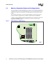
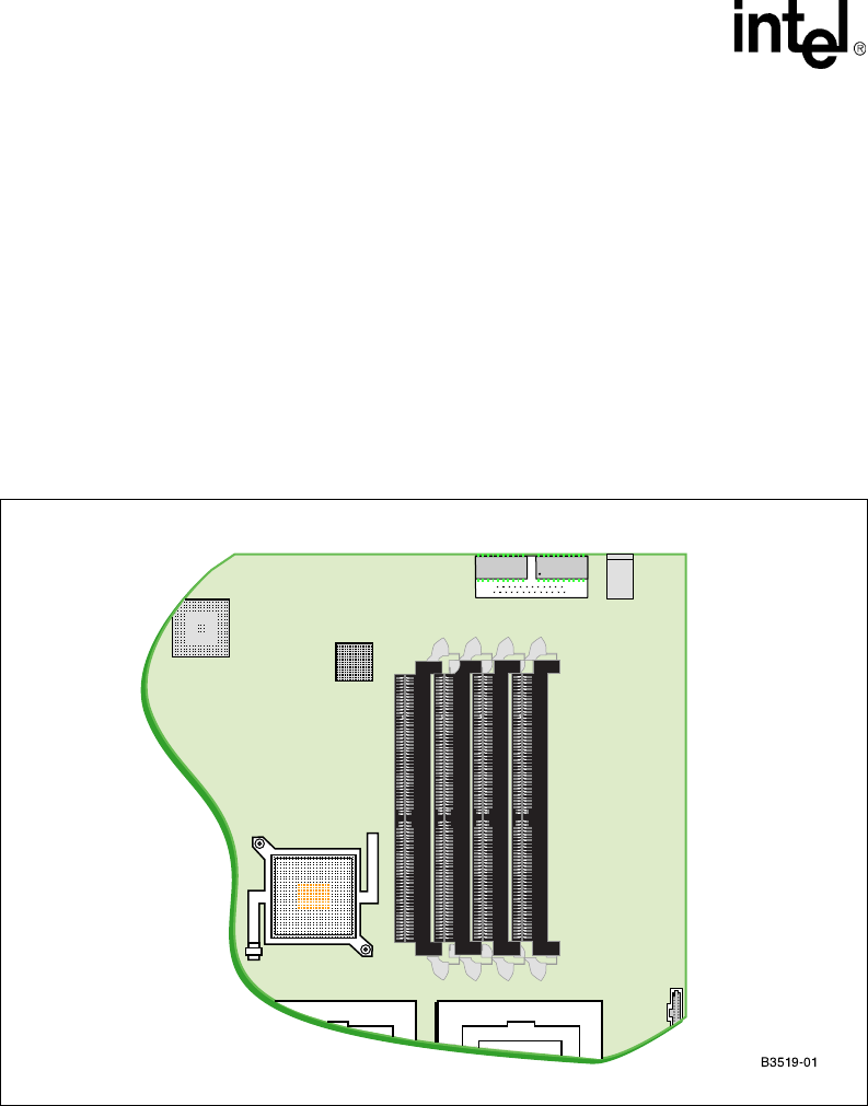
The system supports two DDR2 400 DIMM slots for Channel A and two DDR2 400 DIMM slots
for Channel B. The four slots are interleaved and placed in a row in the following order: A1, B1,
A2, B2, with A1 being closest to the MCH. This design supports only registered ECC-enabled
DIMMs.
When populating both channels, always place identical DIMMs in sockets that have the same
position on Channel A and Channel B (i.e., DIMM A2 should be identical to DIMM B2).
In addition, single-rank DIMMs should be populated furthest when a combination of single-rank
and double-rank DIMMs are used. This recommendation is based on the signal integrity
requirements of the DDR2 interface.
Figure 3. DDR2 400 Memory - DIMM Ordering
+
++
DIMM B2
DIMM A2
DIMM B1
DIMM A1
MCH


