


30 Intel
®
Xeon™ Processor, Intel
®
E7520 Chipset, Intel
®
6300ESB ICH Development Kit User’s Manual
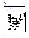
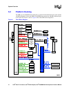
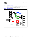
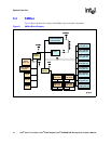
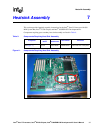
System Overview
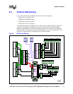
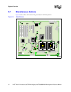
5.6 VRD VID Headers
Provides for manual control of the processor core voltage regulator output level(s). Normally, the
processor should be run at its default VID (voltage identification) value as set during
manufacturing. However, in the event the user needs to set a different VID value from the default
value, it can be accomplished through a jumper block found on the board. Note that these headers
are not populated by default.
The CPU 0 VID header is located at J9K2. CPU 1 VID header is located at J4K1. Table 5 provides
the VID settings available via the VID headers.
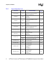
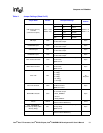
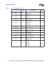
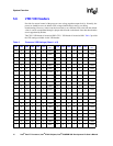
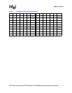
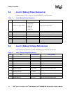
Table 5. Processor VRD Settings (Sheet 1 of 2)
VID5 VID4 VID3 VID2 VID1 VID0
V
CC_MAX
(V)
VID5 VID4 VID3 VID2 VID1 VID0
V
CC_MAX
(V)
0010100.8375 0110101.2125
1010010.8500
1110011.2250
0010010.8625
0110011.2375
1010000.8750
1110001.2500
0010000.8875
0110001.2625
1001110.9000
1101111.2750
0001110.9125
0101111.2875
1001100.9250
1101101.3000
0001100.9375
0101101.3125
1001010.9500
1101011.3250
0001010.9625
0101011.3375
1001000.9750
1101001.3500
0001000.9875
0101001.3625
1000111.0000
1100111.3750
0000111.0125
0100111.3875
1000101.0250
1100101.400
0000101.0375
0100101.4125
1000011.0500
1100011.4250
0000011.0625
0100011.4375
1000001.0750
1100001.4500
0000001.0875
0100001.4625
111111OFF
1011111.4750