Reference Thermal SolutionReference Thermal SolutionReference Thermal Solution
R
18
Intel
®
6700PXH 64-bit PCI Hub Thermal/Mechanical Design Guidelines
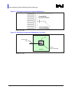
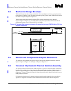
6.3 Mechanical Design Envelope
While each design may have unique mechanical volume and height restrictions or implementation
requirements, the height, width, and depth constraints typically placed on the PXH thermal solution
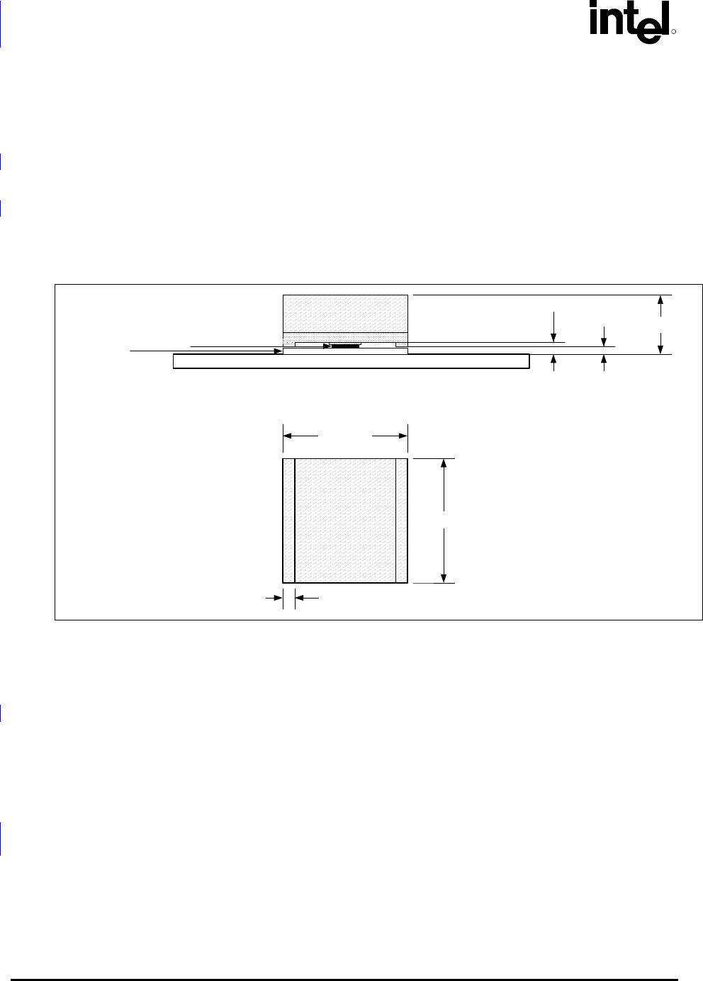
are shown in Figure 6-2Figure 6-2Figure 6-2.
When using heatsinks that extend beyond the PXH reference heatsink envelope shown in
Figure 6-2Figure 6-2Figure 6-2, any motherboard components placed between the heatsink and
motherboard cannot exceed 2.40 mm (0.094 in.) in height.
Figure 6-2. Torsional Clip Heatsink Volumetric Envelope for the Intel
®
6700PXH 64-bit PCI Hub
Chipset Component
Motherboard
Heatsink Base
Die + TIM
FCBGA +
Solder Balls
Heatsink
Fin
Heatsink Fin
31.00mm.
31.00mm.
14.71mm
1.86mm.
3.01mm.
3.00mm.
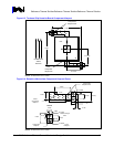
6.4 Board-Level Components Keepout Dimensions
The locations of hole pattern and keepout zones for the reference thermal solution are shown in
Figure 6-3Figure 6-3Figure 6-3 and Figure 6-4Figure 6-4Figure 6-4.
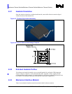
6.5 Torsional Clip Heatsink Thermal Solution Assembly
The reference thermal solution for the PXH component is a passive extruded heatsink with thermal
interface. It is attached using a clip with each end hooked through an anchor soldered to the board.
Figure 6-5Figure 6-5Figure 6-5 shows the reference thermal solution assembly and associated
components. Figure 6-6Figure 6-6Figure 6-6 shows the position of the heatsink rails relative to the
PXH package top surface.
Full mechanical drawings of the thermal solution assembly and the heatsink clip are provided in
Appendix B. Appendix A contains vendor information for each thermal solution component.


