92 Intel 8255x 10/100 Mbps Ethernet Controller Family Open Source Software Developer Manual
Host Software Interface
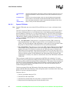
Configuration parameters and contents of other registers are transferred from the CSMA/CD unit
through the status FIFO by the Command Unit to memory. The CU performs the following
sequence:
1. Starts the dump action command.
2. Writes the dump command byte to the transit FIFO.
3. Waits for the dump marker to return from the CSMA/CD module.
4. Dumps the FEXT and CSMA/CD registers content through the status FIFO.
5. Dumps the parallel registers.
6. Prepares the status word with C equal to 1 and the OK bit equal to 1.
7. Completes the action command.
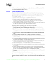
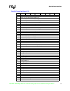
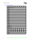
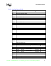
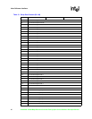
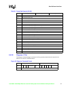
Table 50 and Table 51 describe the dump area format.
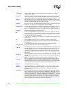
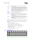
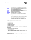
Link Address
This is the 32-bit address of the next command block. It is added to the CU base to
obtain the actual address.
EL (Bit 31)
If this bit is set to one, it indicates that this command block is the last one on the CBL.
The CU will go from the active to the idle state after the execution of the CB is finished.
This transition will always cause an interrupt with the CNA/CI bit set in the SCB.
S (Bit 30)
If this bit is set to one, the CU will be suspended after the completion of this CB. A CNA
interrupt will be generated if the device is configured for this. The CU transitions from the
active to the suspended state after the execution of the CB.
I (Bit 29)
If the I bit is set to one, the device generates an interrupt after the execution of the CB is
finished. If I is not set to one, the CX interrupt will not be generated.
Bits 28:19 These bits are reserved and should all be set to 0.
CMD (Bits 18:16) This is the dump command, which has a value of 110b.
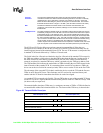
C (Bit 15)
This bit indicates the execution status of the command. Software should reset this bit
before issuing the command to the device. Following a command completion, the device
sets it to one.
NOTE: The difference in the definition of the C bit for the transmit command
(Section 6.4.2.5).
OK (Bit 13)
The OK bit indicates that the command was executed without error. If it equals one, no
error occurred (command executed OK). If the OK bit is zero and the C bit is set, then an
error occurred.
NOTE: The difference in the definition of the C bit for the transmit command
(Section 6.4.2.5).
Buffer Pointer
This field is a 32-bit offset to the dump area address. The size of the dump area is 596
bytes.
Table 50. Dump Data Bytes (0-79)
Byte D7 D6 D5 D4 D3 D2 D1 D0
0 FEXT RCV_WR Base Address Register (low)
1 FEXT RCV_WR Base Address Register (high)
2 FEXT RCV_WR Current Address Register (low)
3 FEXT RCV_WR Current Address Register (high)
4 FEXT RCV_RD Current Address Register (low)


