


Intel Desktop Board D425KT Product Guide
32
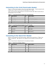
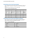
Connecting to the Front Panel Header
Before connecting to the front panel header, observe the precautions in "Before You
Begin" on page 23. See Figure 9, C on page 30 for the location of the front panel
header.
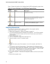
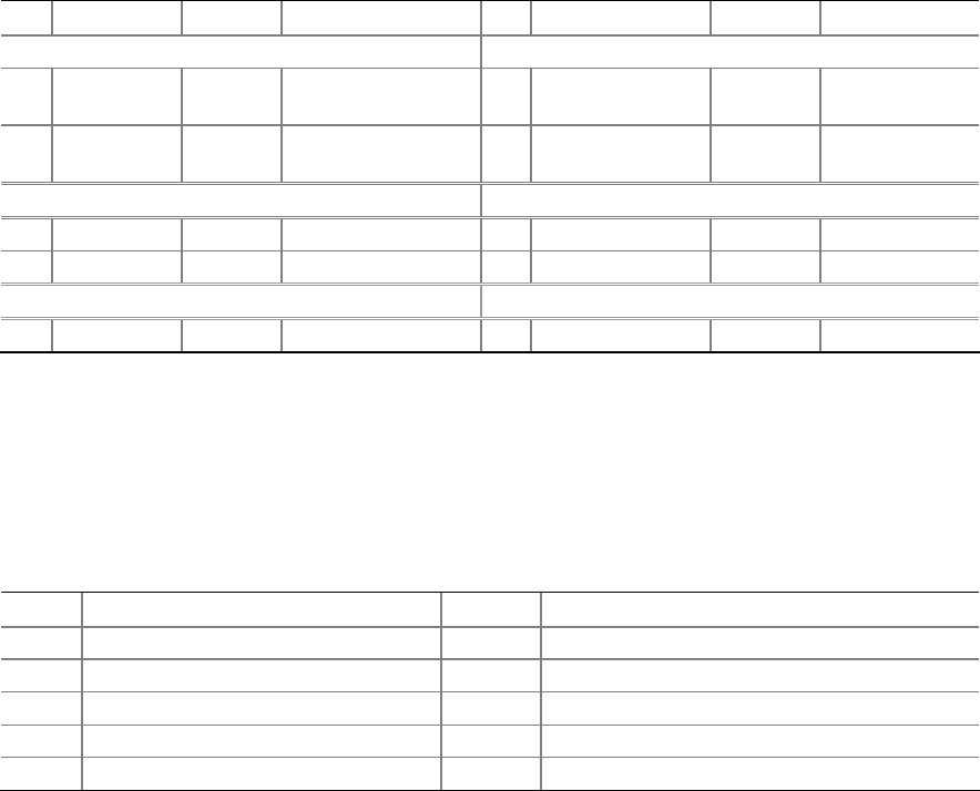
Table 8 shows the pin assignments for the
front panel header.
Table 8. Front Panel Header Signal Names
Pin Signal In/Out Description Pin
Signal In/Out Description
Hard Drive Activity LED Power LED
1 HD_PWR Out
Hard disk LED pull-
up (330 Ω) to +5 V
2 HDR_BLNK_GRN Out
Front panel
green LED
3 HDA# Out
Hard disk active
LED
4 HDR_BLNK_YEL Out
Front panel
yellow LED
Reset Switch On/Off Switch
5 Ground Ground 6 SWITCH_ON# In Power switch
7 FP_RESET# In Reset switch 8 Ground Ground
Power Not Connected
9 +5 V Power 10 N/C No pin
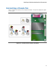
Connecting to the Front Panel USB 2.0 Headers
Before connecting to the USB 2.0 headers, observe the precautions in "Before You
Begin" on page 23. See Figure 9, D on page 30 for the location of the USB 2.0
headers. Table 9 shows the pin assignments for
the headers.
Table 9.
Front Panel USB Headers
Pin Signal Name Pin Signal Name
1
+5 VDC
2
+5 VDC
3
D-
4
D-
5
D+
6
D+
7
Ground
8
Ground
9
KEY (no pin)
10
No Connect