Contents
vii
Figures
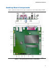
1. Intel Desktop Board D425KT Components........................................................11
2. Back Panel Audio Connectors .........................................................................15
3. LAN Status LEDs ..........................................................................................16
4. Location of the Standby Power Indicator ..........................................................19
5. Installing the I/O Shield ................................................................................26
6. Intel Desktop Board D425KT Mounting Screw Holes...........................................27
7. Installing System Memory .............................................................................28
8. Connecting the Serial ATA Cable .....................................................................29
9. Internal Headers ..........................................................................................30
10. Location of the Chassis Fan Header .................................................................33
11. Connecting Power Supply Cables ....................................................................34
12. BIOS Configuration Jumper Block....................................................................35
13. Removing the Battery ...................................................................................41
14. Intel Desktop Board D425KT China RoHS Material Self Declaration Table..............54
Tables
1. Feature Summary.......................................................................................... 9
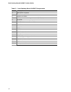
2. Intel Desktop Board D425KT Components........................................................12
3. Audio Jack Support .......................................................................................15
4. LAN Status LEDs ..........................................................................................16
5. Front Panel Audio Header for Intel HD Audio.....................................................31
6. Front Panel Audio Header for AC ‘97 Audio .......................................................31
7. Serial Port Header (COM 1)............................................................................31
8. Front Panel Header Signal Names ...................................................................32
9. Front Panel USB Headers ...............................................................................32
10. Jumper Settings for the BIOS Setup Program Modes..........................................36
11. AcceptableDrives/Media Types for BIOS Recovery .............................................45
12. BIOS Beep Codes .........................................................................................47
13. BIOS Front-panel Power LED Blink Codes.........................................................48
14. POST Error Messages ....................................................................................48
15. Safety Standards..........................................................................................49
16. EMC Regulations...........................................................................................55
17. Regulatory Compliance Marks.........................................................................58
18. ENERGY STAR Requirements..........................................................................60


