


Installing and Replacing Desktop Board Components
49
Connecting to the Serial Port Header
See Figure 23, E for the location of the serial port header. Table 9 shows the pin
assignments for the header.
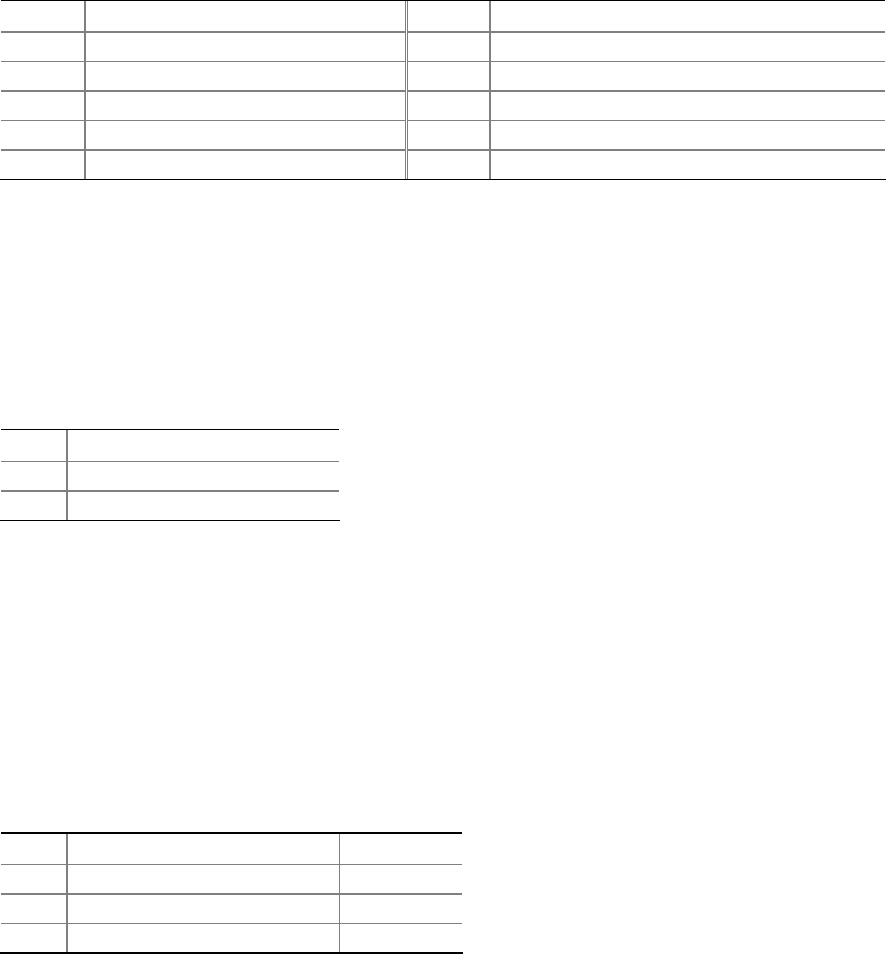
Table 9. Serial Port Header Signal Names
Pin Signal Name Pin Signal Name
1 DCD 2 RXD#
3 TXD# 4 DTR
5 Ground 6 DSR
7 RTS 8 CTS
9 RI 10 No Connection
Connecting to the Chassis Intrusion Header
Figure 23, G on page 46 shows the location of the chassis intrusion header. This
header can be connected to a mechanical switch on the chassis to detect if the chassis
cover is removed.
Table 11 shows the pin assignments for t
h
e chassis intrusion header.
Table 10. Chassis Intrusion Header
Pin Description
1 Intruder
2 Ground
Connecting to the Alternate Front Panel Power LED
Header
Figure 23, H on page 46 shows the location of the alternate front panel power LED
header. Pins 1 and 3 of this header duplicate the signals on pins 2 and 4 of the front
panel header. If your chassis has a three-pin power LED cable, connect it to this
header.
Table 11 shows the pin assignments for th
e altern
ate front panel header.
Table 11. Alternate Front Panel Power LED Header
Pin Description In/Out
1 Front panel green LED Out
2 No pin
3 Front panel yellow LED Out