


Contents
vii
5 Configuring for Intel
®
Rapid Recover Technology
Enabling Intel Rapid Recover Technology...............................................................67
Creating a Recovery Volume................................................................................68
Creating a Recovery Volume Using the RAID Option ROM .................................68
Creating a Recovery Volume Using the Intel Matrix Storage Console ..................68
Disk Synchronization Mode..................................................................................69
Mounting the Recovery Disk ................................................................................69
A Error Messages and Indicators
BIOS Beep Codes...............................................................................................71
BIOS Error Messages..........................................................................................71
B Regulatory Compliance
Safety Regulations .............................................................................................73
Place Battery Marking .................................................................................73
European Union Declaration of Conformity Statement..............................................74
Product Ecology Statements ................................................................................76
Recycling Considerations .............................................................................76
Lead-Free Desktop Board.............................................................................78
EMC Regulations ................................................................................................80
Ensure Electromagnetic Compatibility (EMC) Compliance..................................81
Product Certifications..........................................................................................82
Board-Level Certification Markings ................................................................82
Chassis and Component Certifications............................................................83
Figures
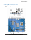
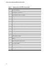
1. Desktop Board DP35DP Components ...............................................................11
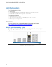
2. LAN Connector LEDs .....................................................................................16
3. Location of the Standby Power Indicator ..........................................................23
4. Installing the I/O Shield ................................................................................27
5. Desktop Board DP35DP Mounting Screw Hole Locations .....................................28
6. Lift the Socket Lever .....................................................................................29
7. Lift the Load Plate.........................................................................................30
8. Remove the Protective Socket Cover ...............................................................30
9. Remove the Processor from the Protective Processor Cover ................................31
10. Install the Processor .....................................................................................31
11. Close the Load Plate .....................................................................................32
12. Connecting the Processor Fan Heat Sink Cable to the Processor Fan Header..........33
13. Dual Channel Memory Configuration with Two DIMMs ........................................35
14. Dual Channel Memory Configuration with Four DIMMs........................................35
15. Dual Channel Memory Configuration with Three DIMMs......................................36
16. Use DDR2 DIMMs .........................................................................................37
17. Installing a DIMM .........................................................................................38
18. Installing a PCI Express x16 Card ...................................................................40
19. Removing a PCI Express x16 Card ..................................................................41
20. Connecting the IDE Cable ..............................................................................43
21. Connecting a Serial ATA Cable........................................................................44
22. Connecting the External Serial ATA Adapter Bracket ..........................................45
23. Internal Headers ..........................................................................................46
24. Back Panel Audio Connectors .........................................................................51
25. Location of the Chassis Fan Headers................................................................52