


LXD9785 PQFP Demo Board with FPGA for SS-SMII (Fiber)-to-MII Conversion
Development Kit Manual 9
Document #: 249323
Revision #: 003
Rev. Date: January 24, 2002
2.0 Introduction
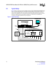
2.1 Overview
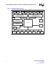
This document describes typical hardware set-up procedures for the LXD9785 PQFP MII Demo
Board. To begin immediate operation, a “Quick-Start Checklist” on page 12 supports 100BASE-
FX operation.
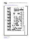
Hardware switches and jumpers allow the designer access to all hardware configuration options.
Each option is outlined in the “Optional Configurations” on page 14.
The Demo Board provides two sets of LED indicators: Direct Drive LEDs and Inter Frame Status
per-port LEDs. The Direct Drive LEDs can be used to display speed, transmit and receive
activities, collision condition, link status, duplex mode, and isolate condition. The Inter Frame
Status LEDs can be used to display full-duplex or half-duplex, 10 Mbps or 100 Mbps, or link.
Board schematics and a Bill of Materials are located in the back of the document.
2.2 Equipment Requirements
The LXD9785 Demo Board is populated with all of the IC components needed for twisted-pair
evaluation. However, the following additional equipment is also required:
• SmartBits Advanced Multi-port Performance Test Box
• PC with Smart Windows (version 6.51 or newer) installed.
• A 3.3V DC Power Supply.
• A 2.5V DC Power Supply.
• Eight MII Cables (male-to-male).
• Eight external NIC cards.
• Eight fiber cables.
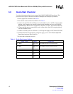
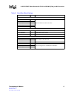
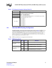
2.3 Fiber Register Configuration
For a register setup via MDIO, proceed with the configuration of the device by setting Register Bit
16.0 to 1 for all ports (see Table 5).