


SSI
EPS1U Power Supply Design Guide, V1.1
6 DC Output Specification
6.1 Connector
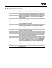
STATUS
Required
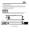
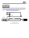
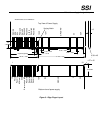
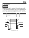
The power supply uses a blind mating type connector with edge fingers (see Figure 1) to connect the power
supply’s output voltages and signals to a connector located in the system. The card edge pin assignments are
listed in Table 6. Figure 3 shows the card edge layout for the power supply. The connector located in the system
is an AMP 1364999-1 or equivalent.
Signals that can be defined as low true or high true use the following convention: signal
#
= low true. Reserved
pins are reserved for future use.
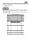
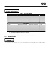
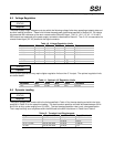
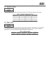
Table 6: Edge Finger Pinout
Description Pin# Pin# Description
-12V 1 62 PSON#
PWOK 2 61 SDA
Reserved 3 60 SCL
ACWarning 4 59 PSAlert#
5VSB 5 58 ReturnS
Removed pin 6 57 Reserved
Reserved 7 56 Reserved
Reserved 8 55 3.3VS
Reserved 9 54 Reserved
Reserved 10 53 Reserved
12V2 11 52 12V2
Keying notch between positions 11 and 12
12V2 12 51 12V2
12V2 13 50 12V2
12V1 14 49 12V1
12V1 15 48 12V1
12V1 16 47 12V1
Ground 17 46 Ground
Ground 18 45 Ground
Ground 19 44 Ground
Ground 20 43 Ground
Ground 21 42 Ground
Ground 22 41 Ground
Ground 23 40 Ground
Ground 24 39 Ground
Ground 25 38 Ground
5V 26 37 5V
5V 27 36 5V
5V 28 35 5V
3.3V 29 34 3.3V
3.3V 30 33 3.3V
3.3V 31 32 3.3V