


SSI
EPS1U Power Supply Design Guide, V1.1
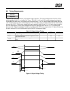
8 Control and Indicator Functions
The following sections define the input and output signals from the power supply.
Signals that can be defined as low true use the following convention:
signal
#
= low true
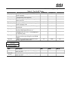
8.1 PSON
#
STATUS
Required
The PSON
#
signal is required to remotely turn on/off the power supply. PSON
#
is an active low signal that turns
on the +3.3 V, +5 V, +12 V, and –12 V power rails. When this signal is not pulled low by the system, or left open,
the outputs (except the +5 VSB and Vbias) turn off. This signal is pulled to a standby voltage by a pull-up resistor
internal to the power supply. Refer to Figure 5 for the timing diagram.
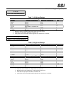
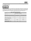
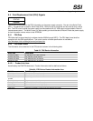
Table 20: PSON
#
Signal Characteristic
Signal Type
Accepts an open collector/drain input from the system.
Pull-up to VSB located in power supply.
PSON
#
= Low
ON
PSON
#
= Open or High
OFF
MIN MAX
Logic level low (power supply ON)
0 V 1.0 V
Logic level high (power supply OFF)
2.0 V 5.25 V
Source current, Vpson = low
4 mA
Power up delay: T
pson_on_delay
5 ms 400 ms
PWOK delay: T
pson_pwok
50 ms
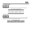
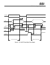
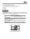
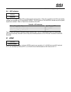
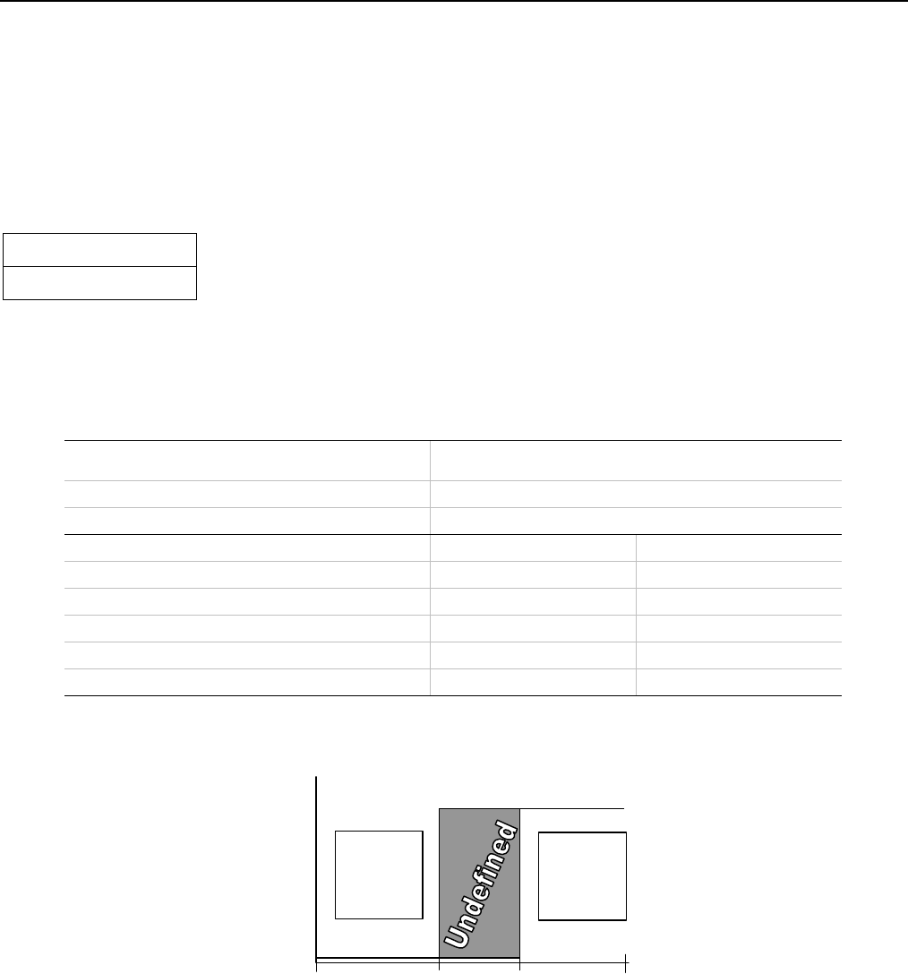
Figure 6: PSON# Signal Characteristics
≤ 1.0 V
PS is
enabled
≥ 2.0 V
PS is
disabled
1.0V
2.0V
Enabled
Disabled
Hysteresis ≥ 0.3V and/or other de-bounce method
5.25V
0V