


7
7
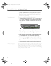
C H A P T E R 1 Intel Express 510T Switch
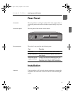
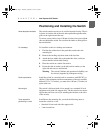
Positioning and Installing the Switch
Allow adequate ventilation The switch contains two fans to air-cool the internal circuitry. The air
is drawn in from the left of the unit and expelled through the outlet
grills on the right side and the rear.
To ensure correct airflow, leave 100 mm (4 inches) free space on both
sides and behind the switch. Do not allow the intake or outlet grills to
become blocked.
On a desktop To install the switch in a desktop environment:
1 Find the four rubber feet in the pack that contains the rack
mounting kit.
2 Remove the backing strip from each of the four feet.
3 Attach the four rubber feet to the underside of the switch (to
ensure that the switch stands firmly).
4 Place the switch on a stable, flat surface.
5 Ensure that the air intake (on the left) and fan outlets (on the
right side and rear) are not blocked.
Warning The switch’s lifetime and operational reliability can
be seriously degraded by inadequate cooling.
Rack requirements Install the switch in a standard rack in accordance with IEC 297 (or
similar); if the minimum outside measurements of the rack are 600 x
600 mm (23.5 x 23.5 inches), you must allow 190 mm (7.5 inches) of
space at the rear.
Mounting kit The switch is delivered with a kit to attach it to a standard 19-inch
equipment rack (with side support rails). The kit contains two mount-
ing brackets and four screws (for attaching the brackets to the sides
of the switch).
Tools required for
positioning in a rack
In addition to the mounting kit, you need the following items to
mount the switch in a rack:
• Standard 19-inch rack with side support rails.
• 3 mm screwdriver.
500.book Page 7 Thursday, September 2, 1999 1:30 PM