


8
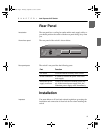
C H A P T E R 1 Intel Express 510T Switch
8
• Customer-supplied screws for securing the switch in the rack.
Mounting screws are not provided because the required sizes
may vary from rack to rack.
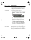
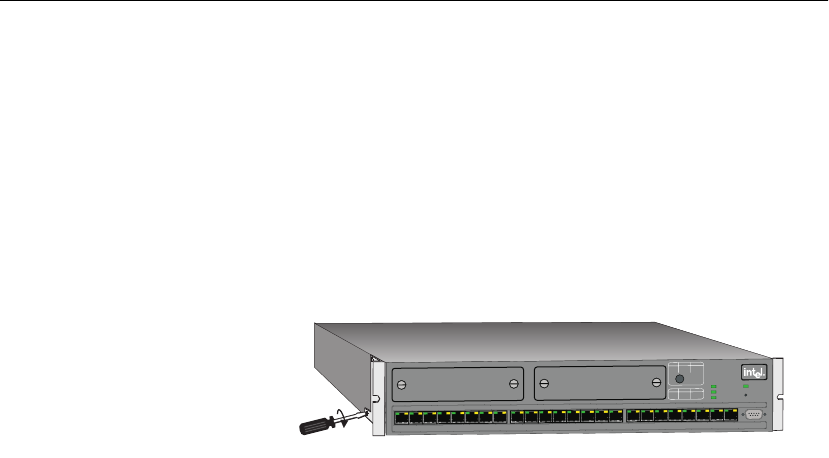
In an equipment rack To mount the switch in a standard equipment rack:
1 Attach the mounting bracket marked “Left” to the left-hand side
of the switch, and attach the mounting bracket marked “Right”
to the right-hand side of the switch, using the four screws pro-
vided.
Make sure that you attach the mounting brackets to the correct
sides. Otherwise the switch will not align correctly in the
equipment rack.
2 If the four rubber feet prevent the switch from standing firmly
on the equipment rack’s side support rails, remove them.
3 Set the switch in the equipment rack, and make sure there is
adequate space for air flow around the switch (see “Allow ade-
quate ventilation” in “Positioning and Installing the Switch”, p.
7).
4 Screw the mounting brackets securely to the equipment rack.
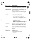
Ambient temperature If the switch is installed in a closed or multi-rack assembly, the oper-
ating ambient temperature of the rack environment may be greater
than the ambient temperature of the room. Make sure that the temper-
ature of the rack environment does not exceed the recommended op-
erating temperature for the switch.
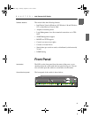
1590
P
o
w
e
r
Intel Express
510T Switch
Sta
tu
s
Te
m
p
e
ra
tu
re
R
P
S
1
2
3
8
7
6
5
4
9
1
0
11
1
6
1
5
1
4
1
3
1
2
1
71
81
9
2
4
2
3
2
2
2
1
2
0
R
e
s
e
t
C
o
n
s
o
l
e
9
6
0
0
-
8
-
N
-
1
S
lo
t
B
S
lo
t
A
B
l
i
n
k
A
c
t
i
v
i
t
y
C
o
l
l
i
s
i
o
n
S
o
l
i
d
L
i
n
k
D
i
s
a
b
l
e
L
E
D
s
G
r
e
e
n
O
r
a
n
g
e
P
o
r
t
S
ta
t
u
s
S
o
l
i
d
1
0
0
M
b
p
s
F
u
l
l
d
u
p
l
e
x
O
f
f
1
0
M
b
p
s
H
a
l
f
d
u
p
l
e
x
L
E
D
s
G
r
e
e
n
O
r
a
n
g
e
500.book Page 8 Thursday, September 2, 1999 1:30 PM