


GA-G1975X Motherboard - 28 -
English
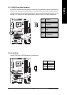
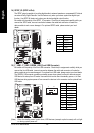
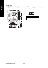
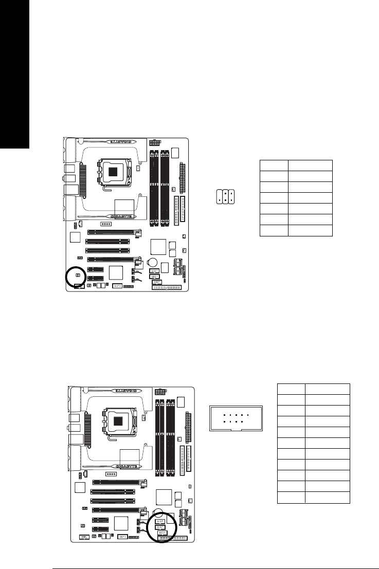
15) F_ USB1 / F_USB2 / GREEN_USB (Front USB Connector)
Be careful with the polarity of the front USB connector. Check the pin assignments carefully while you
connect the front USB cable, incorrect connection between the cable and connector will make the
device unable to work or even damage it. For optional front USB cable, please contact your local dealer.
The GREEN_USB connector provides no standby power when system is off andit does not support
USB device to wake up from S3 mode. Users who wish to shut down the standby power
(note)
for their
USB devices during system power-off can connect the devices to this connector via the optional front
USB cable.
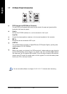
Pin No. Definition
1 Power(5V)
2 Power(5V)
3 USB DX-
4 USB Dy-
5 USB DX+
6 USB Dy+
7 GND
8 GND
9 No Pin
10 NC
1
2
9
10
(Note) When the standby power is shut down, USB devices (example: optical mouses) will not light
on during system power-off.
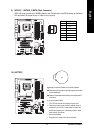
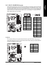
14) SPDIF_IO (SPDIF In/Out)
The SPDIF output is capable of providing digital audio to external speakers or compressed AC3 data to
an external Dolby Digital Decoder. Use this feature only when your stereo system has digital input
function. Use SPDIF IN feature only when your device has digital output function.
Be careful with the polarity of the SPDIF_IO connector. Check the pin assignment carefully while you
connect the SPDIF cable, incorrect connection between the cable and connector will make the
device unable to work or even damage it. For optional SPDIF cable, please contact your local
dealer.
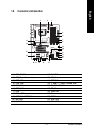
1
62
5
Pin No. Definition
1 Power
2 No Pin
3 SPDIF
4 SPDIFI
5 GND
6 GND