Installation
Page 3-5
3-3 System Memory Configuration
The mainboard accommodates four 240-pin DDR2 DIMM sockets.
• Supports up to 4.0GB of 400/533MHz DDR2 SDRAM.
• Supports dual channel memory interface.
• Supports non-ECC memory and non-Registered DIMMs only.
• Supports 256Mb/512Mb/1Gb DDR2 technologies in x8 and x16 devices only.
• SPD (Serial Presence Detect) scheme for DIMM detection support.
• Supports configurations defined in the JEDEC DDR2 DIMM specification only.
Dual Channel interface:
• Dual channel memory access offers increased system performance.
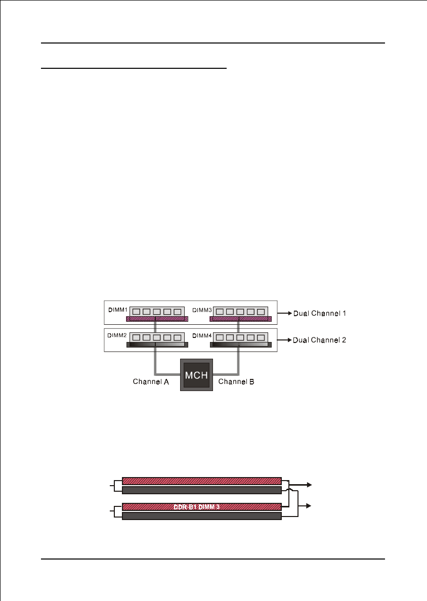
<Figure 7> shows the logical memory layout for channel A and channel B.
• For dual channel to operate, both channel must be populated with same
amount of memory, preferably of the same type.
• The four DIMM sockets are divided into two colors to help you identify the
channel pairs <Figure 8>. Each dual channel pair has the same color, e.g.
DIMM1 and DIMM3. To obtain best performance, simply mount DIMM
sockets of the same color.
DDR-A2 DIMM 2
DDR-B2 DIMM 4
Dual Channel 2
Channel A
Channel B
Dual Channel 1
DDR-A1 DIMM 1
<Figure 8>
<Figure 7>


