


INSTALLATIONS
MI935 User’s Manual 11
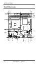
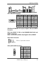
Connectors on MI935
The connectors on MI935 allows you to connect external devices such as
keyboard, floppy disk drives, hard disk drives, printers, etc. The
following table lists the connectors on MI935 and their respective
functions.
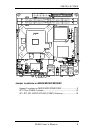
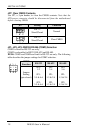
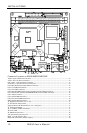
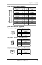
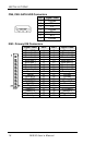
ATX2: 24-pin ATX Power Connector ............................................................. 13
ATX1: ATX 12V Power Connector ................................................................ 13
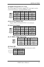
CPU_FAN1: CPU Fan Power Connector ....................................................... 13
SYS FAN1, 2: System Fan Power Connectors ................................................ 13
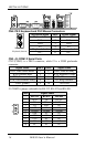
CN4: PS/2 Keyboard and PS/2 Mouse Connectors ......................................... 14
CN2, J3: COM1/2 Serial Ports......................................................................... 14
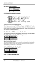
CN1: VGA CRT Connector ............................................................................. 15
CN6: Marvell 88E8053 PCI-express Gigabit LAN and USB2/3 Connector ... 15
CN7: Intel 82562V 10/100 or 82566DM GbE RJ-45 and USB0/1 Connector 15
CN5: Audio Connector .................................................................................... 15
CN3: eSATA HDD Connector ........................................................................ 15
CN9, CN8: SATA HDD Connectors ............................................................... 16
IDE1: Primary IDE Connectors ....................................................................... 16
J2: Digital I/O Connector (4 in, 4 out) ............................................................. 17
J4: For LPC I/F Adaptor Card ......................................................................... 17
Supports ID394 with Fintek F81216, 2 or 4 serial ports .................................. 17
J5: Audio Front Header ................................................................................... 17
J6, J7: USB4/5, USB6/7 Connectors ............................................................... 17
J8: Power LED ................................................................................................. 17
J9: SPDIF Out Connector ................................................................................ 18
J10: System Function Connector ..................................................................... 18
PCIE_1: x16 PCI Express Slot ........................................................................ 18
ID394 LPC Serial Ports Adapter (option) ........................................................ 19