


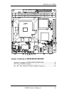
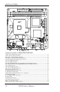
INSTALLATIONS
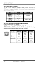
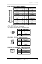
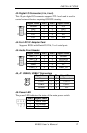
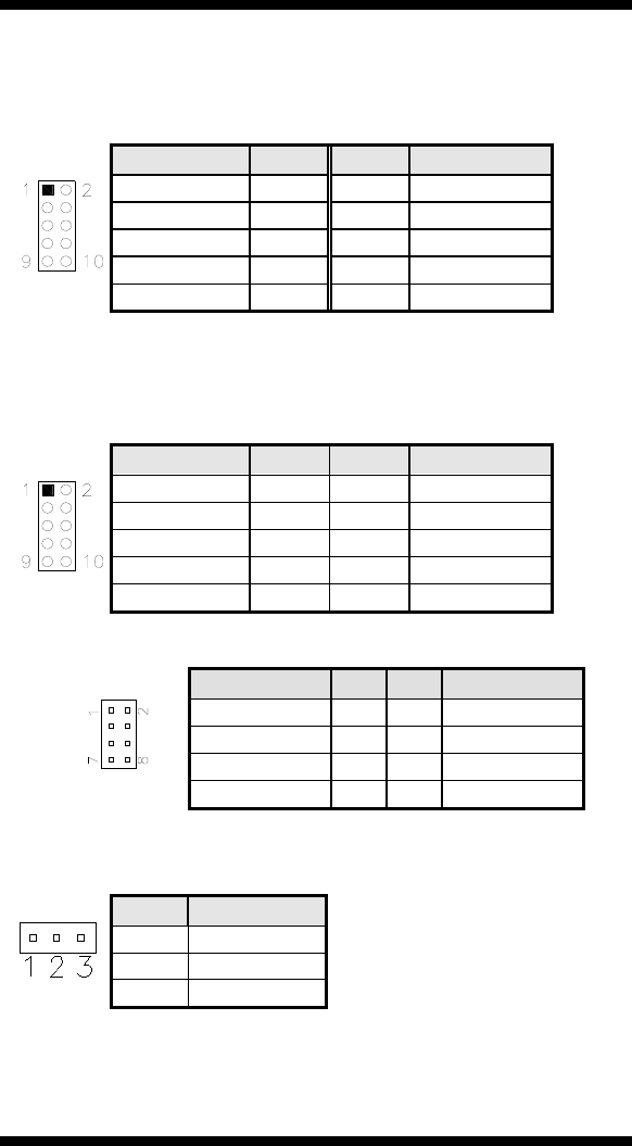
J2: Digital I/O Connector (4 in, 4 out)
This 10-pin digital I/O connector supports TTL levels and is used to
control external devices requiring ON/OFF circuitry.
Signal Name Pin # Pin # Signal Name
Ground 1 2 +5V
Out3 3 4 Out1
Out2 5 6 Out0
IN3 7 8 IN1
IN2 9 10 IN0
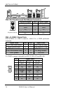
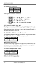
J4: For LPC I/F Adaptor Card
Supports ID394 with Fintek F81216, 2 or 4 serial ports
J5: Audio Front Header
Signal Name Pin # Pin # Signal Name
MIC2_L 1 2 Ground
MIC2_R 3 4 Presence#
Line2_R 5 6 MIC2_ID
Sense 7 8 NC
Line2_L 9 10 Line2_ID
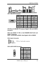
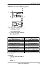
J6, J7: USB4/5, USB6/7 Connectors
Signal Name Pin Pin Signal Name
Vcc 1 2 Ground
USB0- 3 4 USB1+
USB0+ 5 6 USB1-
Ground 7 8 Vcc
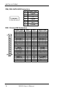
J8: Power LED
The power LED indicates the status of the main power switch.
Pin # Signal Name
1 Power LED
2 No connect
3 Ground
MI935 User’s Manual 17