


INSTALLATIONS
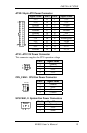
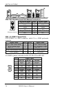
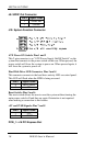
J9: SPDIF Out Connector
Pin # Signal Name
1 SPDIF out
2 Ground
18 MI935 User’s Manual
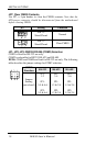
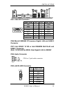
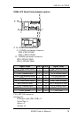
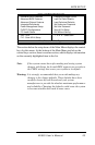
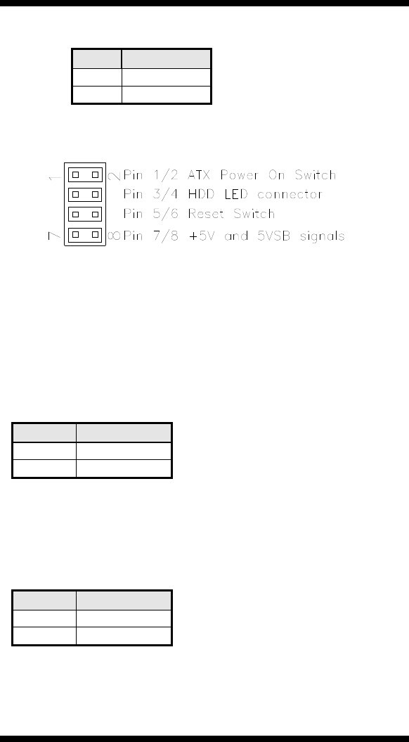
J10: System Function Connector
ATX Power ON Switch: Pins 1 and 2
This 2-pin connector is an “ATX Power Supply On/Off Switch” on the
system that connects to the power switch on the case. When pressed, the
power switch will force the system to power on. When pressed again, it
will force the system to power off.
Hard Disk Drive LED Connector: Pins 3 and 4
This connector connects to the hard drive activity LED on control panel.
This LED will flash when the HDD is being accessed.
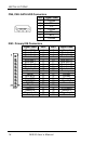
Pin # Signal Name
4 HDD Active
3 5V
Reset Switch: Pins 5 and 6
The reset switch allows the user to reset the system without turning the
main power switch off and then on again. Orientation is not required
when making a connection to this header.
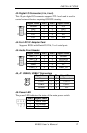
+5V and 5VSB Signals: Pins 7 and 8
Pin # Signal Name
7 +5V
8 +5VSB
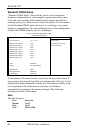
PCIE_1: x16 PCI Express Slot