


2: Key Features & Components
User’s Manual
2•17
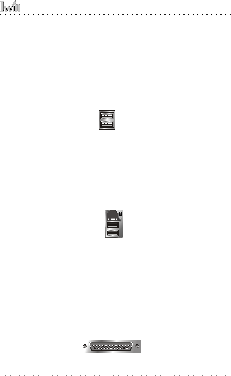
USB Ports
Function: Connecting USB 1.1 devices to the system.
Description: These two ports are for USB 1.1 devices.
The ports are for “Type A” USB cable connectors. You
can connect or disconnect USB cables when the system
is turned on.
More Information: See the Integrated Peripherals sec-
tion of “Configuring the CMOS Setup Utility” in Chapter
5 for information on adjusting port settings.
LAN Port (Optional by Model)
Function: Connecting a CAT 5 LAN cable to the system.
Description: This is an RJ-45 connector for standard Cat
5 LAN cabling with RJ-45 jacks. The connector is for the
optional onboard LAN controller. You can connect or dis-
connect a LAN cable when the system is turned on.
More Information: See the System Features section of
Chapter 6 for information LED modes.
Parallel Port
Function: Connecting a device with a parallel interface
to the system.
Description: The parallel port is generally used to con-
nect a printer to the system. The port supports common
parallel port modes and allows bidirectional communi-
cation. Use an IEEE 1284 compliant cable with the de-
fault ECP mode configuration.
More Information: See the Integrated Peripherals sec-
tion of “Configuring the CMOS Setup Utility” in Chapter
5 for information on adjusting port settings.
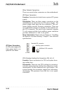
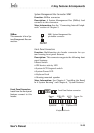
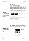
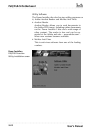
USB ports 1/2 (no LAN option)
USB Ports:
There are two USB ports
on the rear panel. The J65
connector on the board is
for a port bracket with two
more USB ports. Ports 3/4
have a separate root hub.
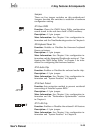
RJ-45 LAN jack
(on top of USB1/2 ports)
LAN RJ-45 Jack:
Upper LED = Activity
Lower LED = Link
Front Panel feature connector
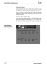
Parallel port:
The default mode is ECP,
configured as EPP 1.9,
DMA 3. 1284 compliant.