


5: System Configuration
User’s Manual
5•5
i
n
t
e
l
m
P
G
A
4
7
8
B
W
8
3
6
3
7
H
F
R
T
L
8
1
0
0
B
+
P
4
D
-
N
V
1
.
1
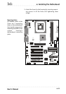
Intel
i845
J39
JP6
CPU
ATX PWR
J79
J9
AGP
PCI1
PCI2
PCI3
PCI4
PCI6
PCI5
IDE1
IDE0
J41
JP1
BT1
FDD
J45
J78
JP16
J65
Front Panel
SMB1
JP12
J75
J66
JP10
J40
J67
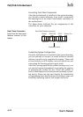
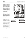
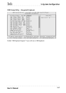
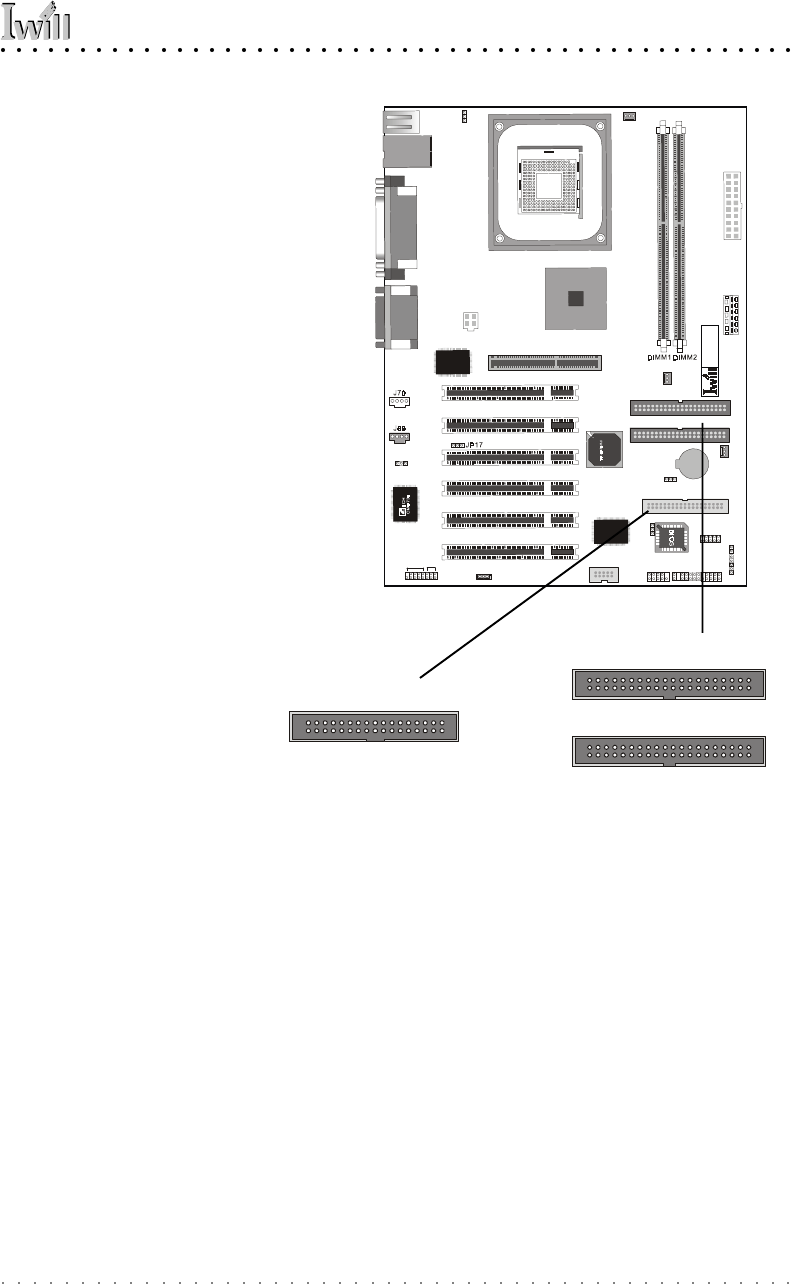
Onboard IDE Connectors
Each channel connector
supports one IDE channel
with two drives, a Master
and a Slave. The Master
drive connects to the con-
nector on the end of the
ribbon cable. The Slave
drive connects to the con-
nector in the middle of
the ribbon cable.
Note:
The ribbon cable used
must support the transfer
mode of the fastest device
connected to it to avoid
degraded performance.
Floppy connector
IDE Primary Channel
IDE Secondary Channel
Floppy Drive Connector
The floppy drive connec-
tor supports two floppy
disk drives. The first drive,
Drive A:, connects to the
connector on the end of
the floppy drive connec-
tor cable. A second drive,
Drive B:, would connect to
the middle connector on
the cable although sys-
tems now commonly only
have one floppy disk drive.