


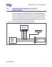
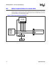
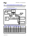
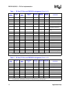

PD672X/30/32/33 — ZV Port Implementation
8 Application Note
A buffer circuit placed between the PC Card bus and the VGA video port reduces the trace length
to lower the loading effect. The ZV Port standard requires that the length of the trace between the
PC Card connector and the buffer (if used) must be less than two inches. Buffers are also needed to
support ZV Port PC Cards in either socket.
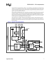
In a full implementation of the ZV Port, multiple PC Card slots can be used to implement the ZV
Port. This implies that the user inserts the multimedia PC Card into either slot and the system is
able to recognize and respond to this event appropriately. To allow the multimedia PC Card to be
inserted into either slot, the individual PC Card bus must be isolated from the other bus by using
buffers in the system. The following block diagrams illustrate possible ZV Port implementations.
Note that the control signal inputs to the buffers can be controlled by different methods. For the
GD7XXX, the buffer control comes from the I/O pins of the GD7XXX that are labeled VPCNTL
and TVON. For further information, refer to the application note titled, “V-Port Implementation for
the GD7548 Super VGA Controller”.