


19
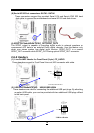
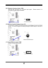
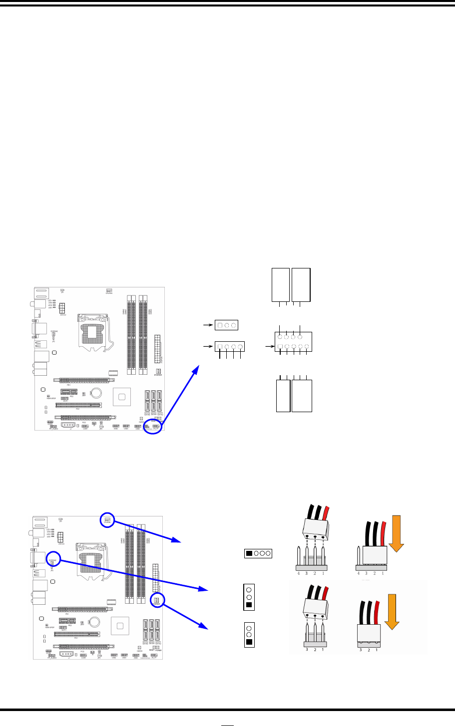
(3) Speaker connector: SPEAK
This 4-pin connector connects to the case-mounted speaker. See the figure
below.
(4) Power LED: PWR LED
The Power LED is light on while the system power is on. Connect the Power
LED from the system case to this pin.
(5) IDE Activity LED: HD LED
This connector connects to the hard disk activity indicator light on the case.
(6) Reset switch lead: RESET
This 2-pin connector connects to the case-mounted reset switch for rebooting your
computer without having to turn off your power switch. This is a preferred method
of rebooting in order to prolong the lift of the system’s power supply. See the
figure below.
(7) Power switch: PWR BTN
This 2-pin connector connects to the case-mounted power switch to power
ON/OFF the system.
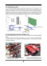
System Case Connections
HDLED
RESET
VC C5
GN D
VCC5
PWR LED
PWRBTN
PWRBTN
PWRLED
HDDLE
RSTSW
NC
GND
JW FP
Pin 1
SPEAK
SPKR
GND
NC
VCC5
Pin 1
PWRLED
Pin 1
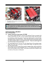
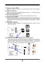
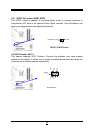
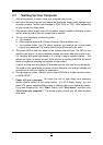
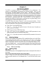
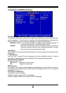
(8) FAN Headers: SYSFAN1, SYSFAN2 (3-pin), CPUFAN1 (4-pin)
These connectors support cooling fans of 350mA (4.2 Watts) or less, depending
on the fan manufacturer, the wire and plug may be different. The red wire
should be positive, while the black should be ground. Please connect the fan’s
plug to the board taking into consideration the polarity of connector.
SYSFAN1
1
3
SYSFAN2
1
3
14
CPUFAN1