


BIOS Intel® Server Board SDS2
Revision 1.2
Order Number: A85874-002
44
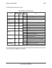
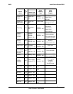
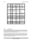
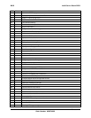
Sensor
Name
Sensor
#
Sensor Type
Event/
Reading
Type
Event
Offset
Triggers
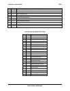
DIMM 6 6Dh
Slot Connector
- 21h
Sensor
Specific - 6Fh
Fault Status
Asserted,
Device Installed,
Disabled
System ACPI
Power State
78h
System ACPI
Power State –
22h
Sensor
Specific - 6Fh
S0 / G0,
S1,
S4,
S5 / G2,
G3 Mechanical Off
Button 79h Button – 14h
Sensor
Specific - 6Fh
Power Button,
Sleep Button,
Reset Button
System
Event
7Ah
System Event –
12h
Sensor
Specific - 6Fh
OEM System Boot
Event (Hard Reset)
SMI Timeout 7Bh
SMI Timeout –
F3h
Sensor
Specific - 6Fh
State Asserted
Sensor
Failure
7Ch
Sensor Failure
– F6h
Sensor
Specific - 6Fh
I
2
C device not found,
I
2
C device error
detected,
I
2
C Bus Timeout
NMI Signal
State
7Dh
OEM - C0h
Digital
Discrete - 03h
-
SMI Signal
State
7Eh OEM - C0h
Digital
Discrete - 03h
-
6.2.4.2 Timestamp Clock
The BMC maintains a four-byte internal timestamp clock used by the System Event Log and
Sensor Data Record subsystems. This clock is incremented once per second and is read and
set using the Get SEL Time and Set SEL Time commands, respectively. The Get SDR Time
command can also be used to read the timestamp clock.
The BMC has direct access the system real-time clock. This allows the BMC to automatically
synchronize the SEL/SDR timestamp clock to the real-time clock time on BMC startup. The
BMC periodically reads the real-time clock to maintain synchronization even when software
asynchronously changes the value. In addition to this, the BIOS send a timestamp to the BMC
using Set SEL Time command during POST.