


Connections Intel® Server Board SDS2
Revision 1.2
Order Number: A85874-002
84
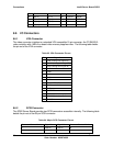
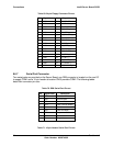
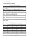
Table 69. 34-pin Floppy Connector Pin-out
Pin Signal Name Pin Signal Name
1 GND 2 FD_DENSEL
3 GND 4 Test Point
5 KEY 6 FD_DRATE0
7 GND 8 FD_INDEX_L
9 GND 10 FD_MTRA_L
11 GND 12 FD_DRVSELB_L
13 GND 14 FD_DRVSELA_L
15 GND 16 FD_MTRB_L
17 GND 18 FD_DIR_L
19 GND 20 FD_STEP_L
21 GND 22 FD_WDATA_L
23 GND 24 FD_WGATE_L
25 GND 26 FD_TRK0_L
27 GND 28 FD_WPT_L
29 GND 30 FD_RDATA_L
31 GND 32 FD_HDSEL_L
33 GND 34 FD_DSKCHG_L
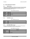
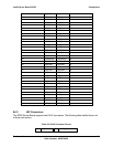
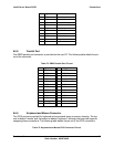
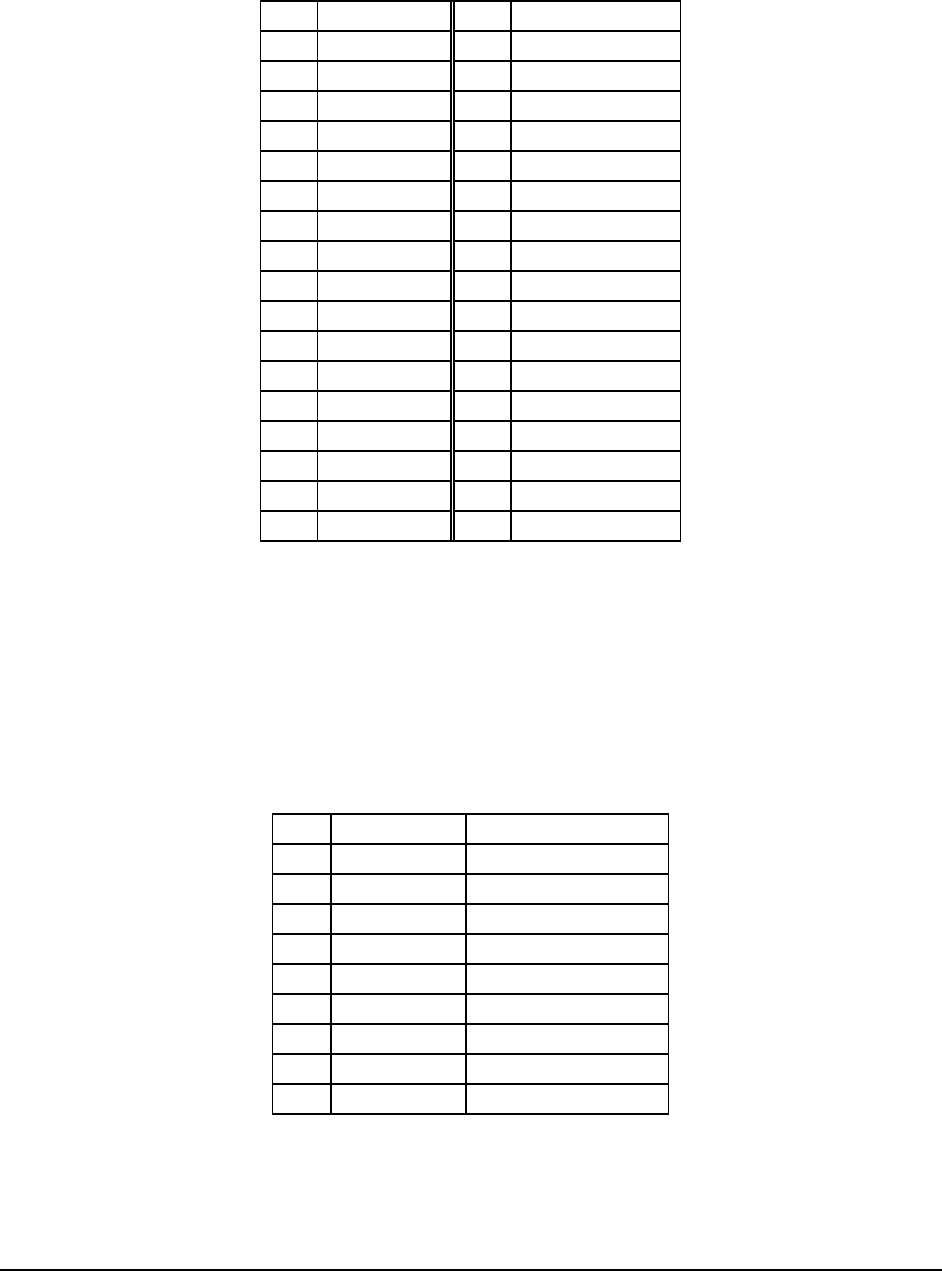
8.6.7 Serial Port Connector
Two serial ports are provided on the Server Board, one DB9 connector is located on the rear I/O
to supply COM1 and a 10-pin header at location CN33 provides COM2. The following tables
detail their connector pin-outs.
Table 70. DB9 Serial Port Pin-out
Pin Signal Name Description
1 DCD Data Carrier Detect
2 RXD Receive Data
3 TXD Transmit Data
4 DTR Data Terminal Ready
5 GND Ground
6 DSR Data Set Ready
7 RTS Request to Send
8 CTS Clear to Send
9 RI Ring Indicate
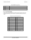
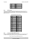
Table 71. 10-pin Header Serial Port Pin-out