


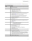

Server Board Features
21
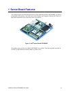
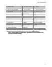
A Chassis Intrusion P CPU Power Connector GG SATA A1
B, Left PCI-X* 100 Slot Q DIMM Sockets HH HSBP B
B, Right PCI-X 100 Slot (MROMB) R CPU 1 Fan Header II Front Panel Connector
C Super I/O S CPU 1 JJ SCSI Channel A
D PCI Slot 32/33 T CPU 2 KK System Fan 1 (3-pin)
E ATI* Rage XL Graphics Controller
U Intel
®
Management
Module Connector
LL System Fan 3 (6-pin)
F, Left x8 (x4speed) PCI-Express* Slot V IDE Connector MM System Fan 4 (6-pin)
F, Right x8 PCI-Express Slot W Floppy Connector NN OEM RMC
G Intel
®
82541P1 (10/100/1000) X System Fan 2 (3-pin) OO ICH5R
H PCI-X 133 Slot Y System Fan 2 (2-pin) PP SCSI Channel B
I Battery Z System Fan 1 (2-pin)
QQ LSI* 53C1030 SCSI
Controller
J ICMB Connector AA HSBP A RR CPU 2 Fan Header
K System Fan 5 BB Front Panel USB SS MCH
L System Fan 6 CC Front Panel LCP TT PHX
M System I/O Connectors DD IPMB UU Serial B Header
N Auxiliary Power Connector EE SATA A2
O Main Power Connector FF Speaker
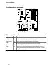
Note: F, Right (x8 PCI Express), NN (OEM RMC), and PP (SCSI Channel B) are not available on product codes
SE7520BD2VD2. QQ (LSI* 53C1030 SCSI Controller) is not available on product code SE7520BD2SATAD2.
Figure 3. Product Codes SE7520BD2SCSID2, SE7520BD2VD2, and SE7520BD2SATAD2
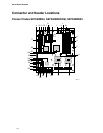
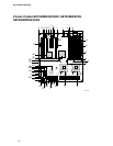
Connector and Header Locations