


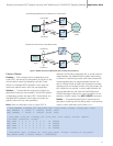

Table 1 compares the advantages and disadvantages of these methods.
Table 1. Comparison of a Straight Link Configuration vs. a Crossed Link Configuration
Comparison Subject Straight Configuration Crossed Configuration
Load sharing -+
STPA can only load share traffic Each STP can load share between the two SIUs,
for SIUA and vice-versa optimizing the resource utilization
Network-facing links +-
failure SIUA can rely on SIUB to send When an SIU loses its network-facing links, the
outgoing traffic upon failure of its application must activate circuit groups on the
entire network-facing links surviving SIU (for ISUP-based application)
Inter-SIU link set -+
dimensioning Need to allocate 1/4 of all Need to allocate a single link, maximizing the
network facing links (e.g., 16 number of network-facing links (e.g., 22 network facing
network facing links and four links and one inter-SIU link). Allocating a single link means
inter-SIU links) there are two single points of failure in the system.
For best resilience, the inter-SIU link set should contain
two links spread across two cards in each SIU.
Building Fault-tolerant SS7 Systems Using the Intel
®
NetStructure™ SIU520 SS7 Signaling Gateway Application Note
9
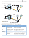
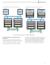
SSP/SCP
STPA
STPB
Link Set id 1
Link Set id 2
C-Links
A-Links
Link Set id 0
Transmit Traffic from SIUA
Transmit Traffic from SIUB
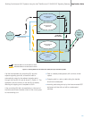
SSP/SCP
Inter-SIU
Link Set
STPB
Link Set id 1
C-Links
A-Links
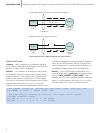
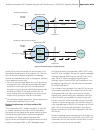
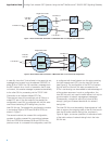
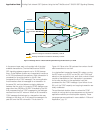
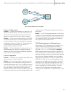
B) Routing under failure of network link set between SIUA and adjacent STP
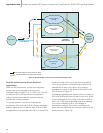
A) Normal routing case (both network link sets available)
SIUA
SIUB
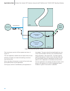
SIUA
SIUB
Single Point Code
Single Point Code
Link Set id 0
Link Set id 2
Inter-SIU
Link Set
Figure 9. Transmit Routing Through Mated STPs