


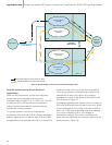
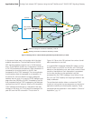
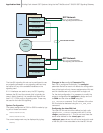
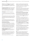
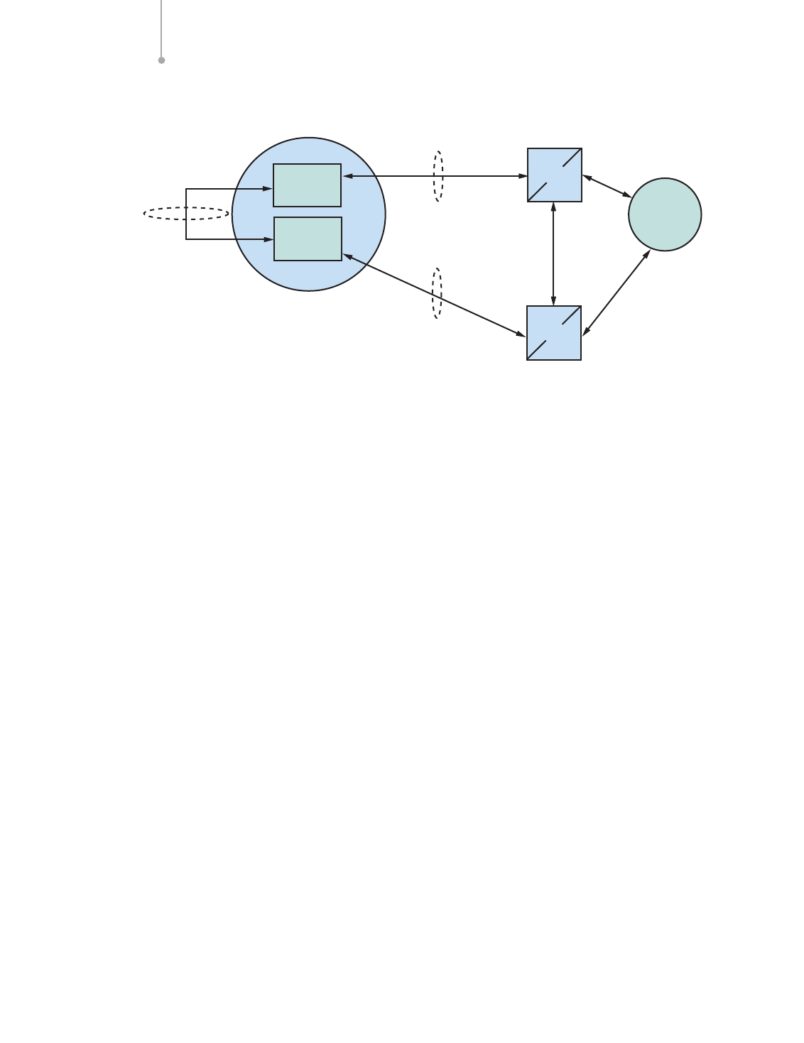
For an SIU pair connected to a mated STP pair, carrying
the inter-SIU link over the second E-1 port of the first
signaling card the configuration (Figure 20) would be:
For SIUA
MTP_CONFIG 0 0 0x0000
MTP_LINKSET 0 300 1 0x8000 300 0x8
MTP_LINKSET 1 400 1 0x0000 300 0x8
MTP_LINK 0 0 0 0 1 1 1 1 0 0x4006
MTP_LINK 1 1 0 0 1 2 1 2 16 0x0006
MTP_ROUTE 300 0 0x0020
MTP_ROUTE 400 1 0x0020 0x0001 0
MTP_ROUTE 500 1 0x0020 0x0001 0
MTP_ROUTE 600 1 0x0020 0x0001 0
For SIUB
MTP_CONFIG 0 0 0x0000
MTP_LINKSET 0 300 1 0x8000 300 0x8
MTP_LINKSET 1 500 1 0x0000 300 0x8
MTP_LINK 0 0 0 0 1 1 1 1 0 0x6006
MTP_LINK 1 1 0 0 1 2 1 2 16 0x0006
MTP_ROUTE 300 0 0x0020
MTP_ROUTE 400 0 0x0020 0x0001 0
MTP_ROUTE 500 1 0x0020 0x0001 0
MTP_ROUTE 600 1 0x0020 0x0001 0
Run-time Operations of a Dual-resilient
SIU System
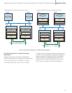
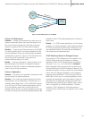
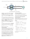
Connecting a Host to Two SIUs
In a dual SIU system, each host should connect to both
SIUA and SIUB at start-up. This is achieved using the
rsicmd utility twice: first with an siu_id of 0 for SIUA and
second with an siu_id of 1 for SIUB. For example, if
SIUA has an IP address of 123.234.345.110 and SIUB
an IP address of 123.234.345.220, the entry in the host’s
system configuration file, system.txt, would be:
FORK_PROCESS rsicmd 0 0xef 0
123.234.345.110 9000
FORK_PROCESS rsicmd 1 0xef 0
123.234.345.220 9000
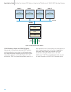
The “concerned module id” (0xef in this case) will
receive status indications from the rsi process for both
connections. The id field of the MSG header is set to the
siu_id to identify the link that each status indication
relates to.
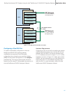
The ability to communicate between a host and an SIU is
indicated by RSI_MSG_STATUS messages received by
the conc_id application process (0xef in this case).
Application Note Building Fault-tolerant SS7 Systems Using the Intel
®
NetStructure™ SIU520 SS7 Signaling Gateway
20
Link Set id 0
Point
Code 300
Inter-SIU
Link Set
Point
Code 400
Point
Code 500
Link Set id 1
link_id 1, slc 0
Point
Code 600
link_id 1, slc 0
SIUA
SIUB
STPA
STPB
SSP/SCP
Link Set id 1
Single Point
Code
Figure 20. Example Configuration to an Adjacent STP Pair