


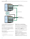
using the MTP_LINK command, assigning incrementing
<link_ref> and <slc> values as normal. The <bpos>
and <blink> parameters define which SS7 processor
(there are three on each signaling card) manages each
link. If a V.11 port is being used, <blink> must be either
1 or 2.
For a link using a PCM port, the physical location of the
link is specified by setting stream and timeslot: stream 16
is the PCM port closest to the green LED on the signaling
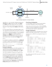
card, stream 17 the lower PCM port. To use a serial link,
the MTP_LINK <flags> bit 14 should be set to 1,
<stream> and <timeslot> both to 0. One of the units
should act as the V.11 port clock master, the other as
slave; hence, one SIU must also have <flags> bit 13
set to 1.
For example, to configure an inter SIU link, on linkset_id
0, to use V.11 port A on the first board in a SIU520, this
command would be used to define a V.11 clock slave:
MTP_LINK 0 0 0 0 1 1 1 1 0 0x4006, while
MTP_LINK 0 0 0 0 1 1 1 1 0 0x6006 would
define a V.11 port clock master.
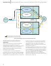
Routing Configuration
A route should be defined on both SIUA and SIUB for the
inter-SIU link set using the MTP_ROUTE command
referencing the appropriate <linkset_id> with a <dpc>
value set to the point code of the SIU pair. This route
may only be specified to operate over a single link set.
Each DPC that may be accessed from the application
must have an accompanying MTP_ROUTE declaration.
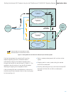
For dual operation, each route includes a preferred link
set, the <linkset_id> parameter, and a secondary link
set specified by <second_ls>. linkset_id should refer-
ence the link set connecting the SIU to the appropriate
adjacent signaling point, second_ls must be set to the
linkset_id assigned to the inter-SIU link set.
Circuit Group Configuration
For dual operation, each SIU should contain identical
circuit group declarations using the appropriate
ISUP_CFG_CCTGRP or TUP_CFG_CTGRP commands.
These circuit group configurations do not become active
on either unit until an Activate Circuit Group API
command has been issued to a particular SIU.
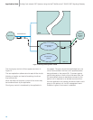
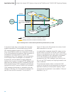
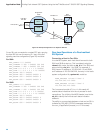
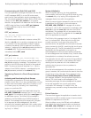
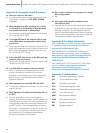
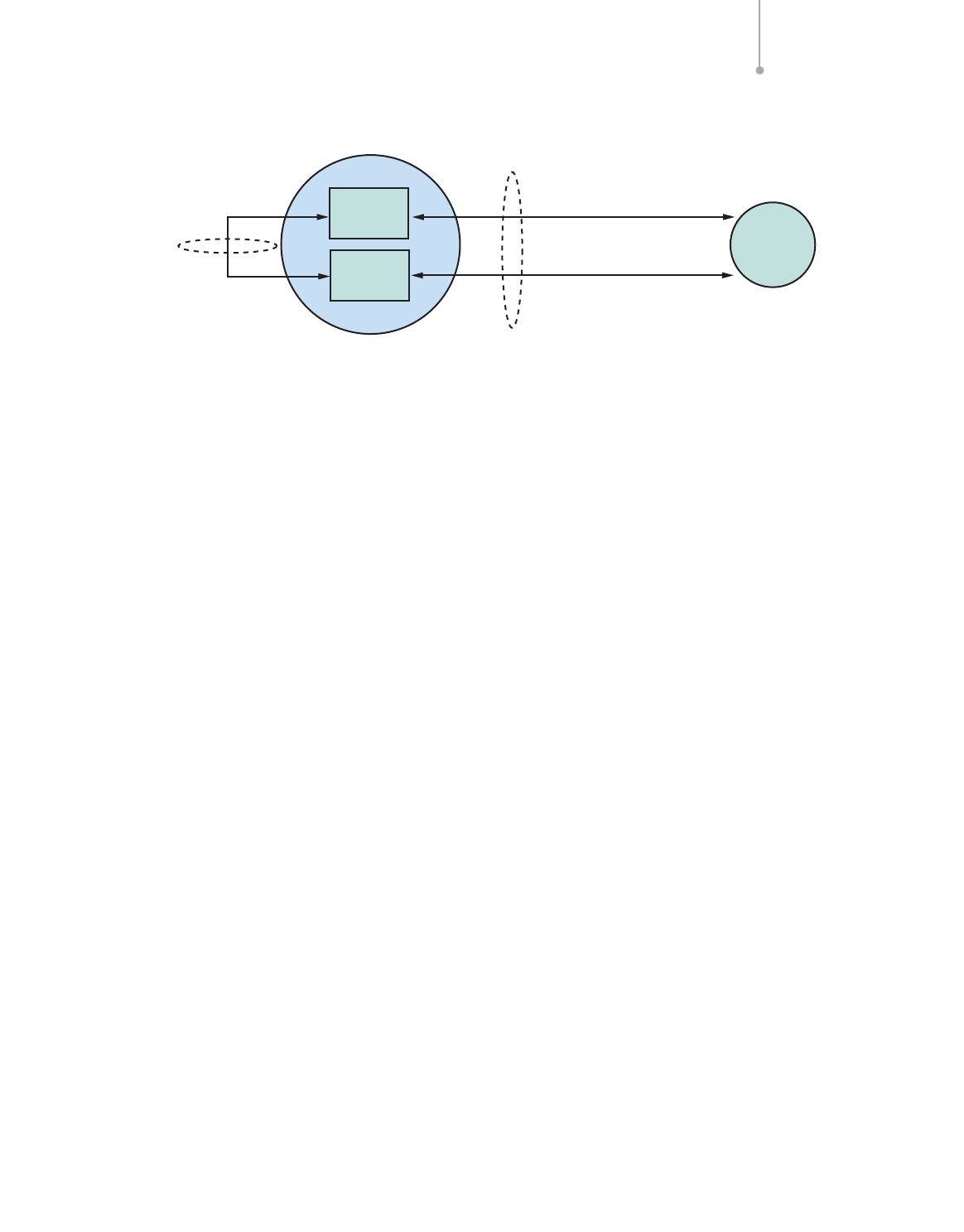
Example Configuration
To define routing to the DPC 200 below (which is also the
adjacent point code), using the first E-1 port on the first
signaling card in a SIU520, the configuration (Figure 19)
would be
For SIUA
MTP_CONFIG 0 0 0x0000
MTP_LINKSET 0 100 1 0x8000 100 0x8
MTP_LINKSET 1 200 1 0x0000 100 0x8
MTP_LINK 0 0 0 0 1 1 1 1 0 0x4006
MTP_LINK 1 1 0 0 1 2 1 2 16 0x0006
MTP_ROUTE 100 0 0x0020
MTP_ROUTE 200 1 0x0020 0x0001 0
For SIUB
MTP_CONFIG 0 0 0x0000
MTP_LINKSET 0 100 1 0x8000 100 0x8
MTP_LINKSET 1 200 1 0x0000 100 0x8
MTP_LINK 0 0 0 0 1 1 1 1 0 0x6006
MTP_LINK 1 1 0 1 1 2 1 2 16 0x0006
MTP_ROUTE 100 0 0x0020
MTP_ROUTE 200 1 0x0020 0x0001 0
(up_enable was set for ISUP, user part SI = 5 for the
example above)
Building Fault-tolerant SS7 Systems Using the Intel
®
NetStructure™ SIU520 SS7 Signaling Gateway Application Note
19
Figure 19. Example Configuration to an Adjacent SSP/SCP
Link Set id 1
Inter-SIU
Link Set
Point
Code 100
Link_id 0,
slc 0
Link id 1, slc 0
Link id 1, slc 1
Point
Code 200
SIUA
SIUB
SSP/SCP
Link Set id 0
Single Point
Code