


Dual SIU Architecture for Circuit-Switched
Applications
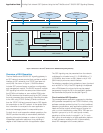
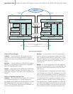
Within the SIU environment, circuits are configured in
groups, each group equating to all the circuits
multiplexed onto a single E-1 or T-1 PCM trunk. The SIU
provides the SS7 circuit control and the application
platform (or host) terminates the physical channels,
typically with a voice processor.
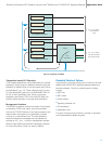
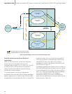
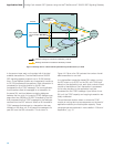
For normal operation, half the circuit groups are
controlled by SIUA and half by SIUB. As each application
platform starts up and connects to both SIUA and SIUB,
the application must nominate which SIU is to control the
signaling for each of the circuit groups it terminates. A
circuit group activation command must be sent to the
selected SIU for each circuit group. Any outgoing
messages for circuits in this group must be sent to this
SIU, as shown in Figure 10.
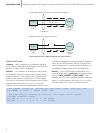
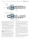
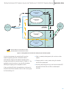
The adjacent signaling point views the links connected to
SIUA and SIUB as the same link set and, as such, is free
to send messages for the circuits controlled by SIUA to
either unit. In the case where SIUB receives a message
for a circuit controlled by SIUA, the message is
automatically routed to the correct controlling circuit
group using the LAN Ethernet connection (shown by the
shaded arrows in Figure 10).
Application Note Building Fault-tolerant SS7 Systems Using the Intel
®
NetStructure™ SIU520 SS7 Signaling Gateway
10
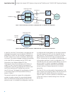
Figure 10. Normal Routing for Circuit Group 0 When Controlled by SIUA
SIUB
MTP1-3
Circuit Group 0
[Active]
Circuit Group 1
[Inactive]
Circuit Group 0
[Inactive]
Circuit Group 1
[Active]
Adjacent
Signaling
Point
Application
TCP/IP Ethernet
Inter-SIU
SS7 Link Set
SIUA
MTP1-3
SS
7
SS7
Transmit traffic for circuits active on SIUA
Received traffic for circuits active on SIUA