


30
Appendix B
Connector Pin Assignments
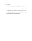
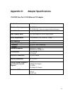
Each of the Four 8-pin MJ connectors for 10/100 Mb/sec are wired as shown in Figure 2:
Figure 2 8-Pin MJ Connector (Front)
With the connection pins assigned as shown in Table 5:
Pin Number Signal Name
1 Transmit + TX (+)
2 Transmit - TX (-)
3 Receive + RX (+)
4 No Connection NC
5 No Connection NC
6 Receive - RX (-)
7 No Connection NC
8 No Connection NC
Table 5 8-Pin MJ Connector Pin Assignments
Connection from the ITI-5232 adapter to a network hub must be made as shown in
Table 6:
Straight Through
Adapter Pin Hub Pin
TX (+) 1
ÇÈ
1RX (+)
TX (-) 2
ÇÈ
2RX (-)
RX (+) 3
ÇÈ
3TX (+)
44
55
RX (-) 6
ÇÈ
6TX (-)
77
88
1 2 3 4 5 6 7 8