


SECTION 5—WHEELCHAIR OPERATION
Part No 1143190 39 TDX™ SP
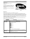
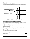
Information Gauge Display
Theinformationgaugedisplayislocatedonthefrontofthejoystickhousingandprovides
thefollowinginformationtotheuseronthestatusofthewheelchair:
1. PowerisOn.
2. Truestate‐of‐battery‐charge,includingnotificationofwhenthebatteryrequires
charging:
A. GREENLEDsarelit,indicatingwellchargedbatteries.
B. AMBERLEDsarelit,indicatingbatteriesaremoderatelycharged.Recharge
batteriesbeforetakingalongtrip.
C. REDLEDsarelit,indicatingbatteriesarerunningoutofcharge.Rechargebatteries
assoonaspossible.
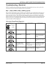
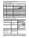
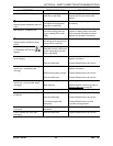
TheInformationGaugedisplayalsoservesasasystemdiagnosticdevicewhenafaultis
detectedbythecontrolmodule.AspecificnumberofflashesoftheLEDsindicatethetype
offaultdetected.RefertoServiceIndicatorLightDiagnosticsonpage 30forthe
diagnosticindicationsofthewheelchairstatus.
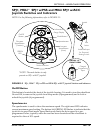
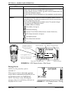
MPJ+ Joystick Switches and Indicators
NOTE:Forthisprocedure,refertoFIGURE 5.4onpage 40.
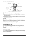
Drive Select Toggle Switch
Thedriveselecttoggleswitchislocatedontheleftside,belowtheLCD.Thedriveselect
positionismomentary,meaningthatitwillreturntotheneutralpositionafteraselection
ismade.
Thisswitchallowstheoperatorto selectthetypeofoperationorperformancewhichbest
suitsaparticularcontrolneedorsituation.TheDRIVE1programusesperformance
valueswhichareindependentofthoseusedfortheDRIVE2or3or4program.Asan
example,anoperatormayhaveacontrolneedforspasticityinthemorningandavery
differentneedintheafternoon.DRIVE
1canbeprogrammedforhigherspeedsand
quickerresponsewhileDRIVE2canbeprogrammedforslowerspeedsandless
responsivenessorviseversa.Theothertwodriveprogramscouldbeindoorandoutdoor
versionsofDRIVE1andDRIVE2.
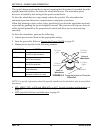
Selecting the Drive Mode
1. Movethetoggleupandrelease.DRIVE1
()willappearonLCD.
2. Movethetoggleupandreleaseagain.DRIVE2()willappearonLCD.
3. Movethetoggleupandreleaseagain.DRIVE3()willappearonLCD.
4. Movethetoggleupandreleaseagain.DRIVE4()willappearonLCD.
5. MovethetoggleupandreleaseonemoretimetoselectDRIVE1().