


Coaxial Networks, Inc. Page 13 of 60
IRIS Rear Panel Connections
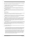
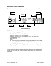
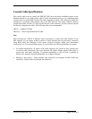
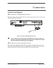
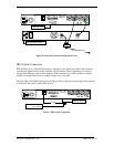
The diagram below illustrates the relevant rear panel ports and connections on the IRIS.
100 Mbps
Ethernet Uplink
Port
Coax Receive
Port
Coax Transmit
Port
Male DB9 Serial
Console Port
Autoswitching
110/230V Power
Supply
UPLINK
CONSOLE PWR
TX
Power Supply
Cooling Fan
RX1
ACT
RF ON
Air
Ventilation
RX2
Figure 1 IRIS Rear Panel
IRIS Rear Panel consists of the following connectors and labels
1. Auto switching 110V/230V power supply connector
2. Female ‘F’ Connector for coax Transmit
3. Female ‘F’ connector for coax Receive channel 1
4. Female ‘F’ connector for coax Receive channel 2 (for DC1200 models only)
5. Uplink Ethernet RJ-45 port
6. Serial console port
7. LEDs:
• Power (PWR) LED: Green when the power is connected and the system power up.
• Activity (ACT) LED: Amber/Yellow LED Blinks indicating Up Stream data transfer
is active.
• RF ON LED: Green LED is lit when the Up converter is successfully powered on.
8. Rack mounting Ears (not shown): IRIS chassis has a provision for mounting the chassis
backwards if customer desires.
The above-mentioned connectors are mainly required for configuration and operation of IRIS.
The rear panel may contain other connectors for future features and the user should currently
ignore them.