


EX2500 Ethernet Switch Configuration Guide
26 VLAN Topologies and Design Considerations
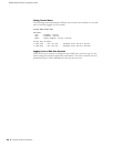
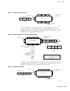
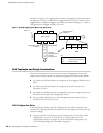
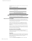
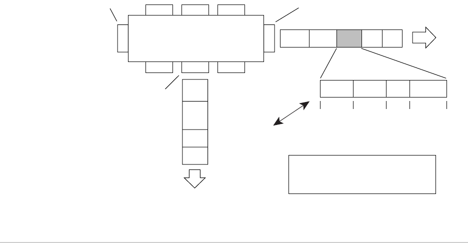
As shown in Figure 5, the tagged packet remains unchanged as it leaves the switch
through port 5, which is configured as a tagged member of VLAN 2. However, the
tagged packet is stripped (untagged) as it leaves the switch through port 7, which is
configured as an untagged member of VLAN 2.
Figure 5: 802.1Q Tagging (after 802.1Q Tag Assignment)
VLAN Topologies and Design Considerations
This section discusses how you can connect users and segments to a host that
supports many logical segments or subnets by using the flexibility of the multiple
VLAN system. Be aware of the following VLAN properties on the EX2500 switch:
By default, the EX2500 software is configured so that tagging is disabled on all
ports.
By default, the EX2500 software is configured so that all data ports are
members of VLAN 1.
By default, the EX2500 software is configured so that the management port is a
member of VLAN 4095 (the management VLAN).
If you configure Spanning Tree, note that Spanning Tree Groups 2-128 are
allowed to contain only one VLAN.
VLAN Configuration Rules
VLANs operate according to specific configuration rules. When creating VLANs,
consider the following rules that determine how the configured VLAN reacts in any
network topology:
All ports involved in trunking and port mirroring must have the same VLAN
configuration. If a port is on a trunk with a mirroring port, the VLAN
configuration cannot be changed. For more information trunk groups, see
“Port Trunking Configuration Example” on page 45.
BS45014A
Port 6 Port 7 Port 8
Port 1
Port 4
Port 5
Port 2 Port 3
802.1Q Switch
Key
Priority
CFI
VID
- User_priority
- Canonical format indicator
- VLAN identifier
PVID = 2
Tagged member
of VLAN 2
Untagged member
of VLAN 2
After
DA
SA
Data
CRC*
(*Recalculated)
Outgoing
untagged packet
changed
(tag removed)
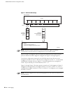
DASADataCRC Tag
VID = 2Priority
16 bits 3 bits 1 bit 12 bits
8100 CFI