


EX2500 Ethernet Switch Configuration Guide
40 Multiple Spanning Tree Protocol
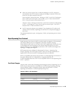
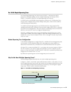
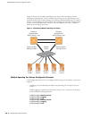
Figure 9 shows how multiple spanning trees can provide redundancy without
wasting any uplink ports. In this example, the server ports are split between two
separate VLANs. Both VLANs belong to two different Multiple Spanning Tree (MSTP)
Groups. The spanning-tree priority values are configured so that each routing switch
is the root for a different MSTP instance. All of the uplinks are active, with each
uplink port backing up the other.
Figure 9: Implementing Multiple Spanning Tree Groups
Multiple Spanning Tree Groups Configuration Example
This configuration shows how to configure MSTP Groups on the switch, as shown in
Figure 9.
1. Configure port membership and define the Spanning Tree Groups (STGs) for
VLAN 1.
Enable tagging on uplink ports that share VLANs. Port 19 and port 20 connect
to the Enterprise Routing switches.
ex2500(config)# interface port 19
ex2500(config-if)# tagging
ex2500(config-if)# exit
ex2500(config)# interface port 20
ex2500(config-if)# tagging
ex2500(config-if)# exit
Enterprise
Routing Switch
Enterprise
Routing Switch
Blocking VLAN 1
Passing VLAN 2
Passing VLAN 1
Blocking VLAN 2
(MSTP Group 1 root)
(MSTP Group 2 root)
Server 1
VLAN 2
Server 2
VLAN 2
Server 3
VLAN 1
Server 4
VLAN 1
Server 5
VLAN 1
EX2500
Switch