


Installing a DC Power Supply
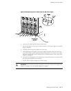
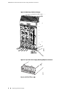
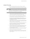
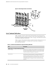
To install a DC power supply, follow this procedure (see Figure 5 on page 9):
1. Ensure that the voltage across the DC power source cable leads is 0 V and that
there is no chance that the cable leads might become active during installation.
CAUTION: You must ensure that power connections maintain the proper polarity.
The power source cables might be labeled (+) and (–) to indicate their polarity. There
is no standard color coding for DC power cables. The color coding used by the external
DC power source at your site determines the color coding for the leads on the power
cables that attach to the terminal studs on each power supply.
2. Attach an electrostatic discharge (ESD) grounding strap to your bare wrist and
connect the strap to one of the ESD points on the chassis. For more information
about ESD, see the MX960 Ethernet Services Router Hardware Guide.
3.
Switch the circuit breaker on the power supply faceplate to the OFF position.
4. Ensure that the release lever below the empty power supply slot is engaged in
the counterclockwise, or unlocked, position (see Figure 5 on page 9).
If necessary, pull the spring-loaded locking pin in the release lever away from
the chassis and turn the release lever counterclockwise until it stops. Let go of
the locking pin in the release lever. Ensure that the pin is seated inside the
corresponding hole in the chassis.
5. Using both hands, slide the power supply straight into the chassis until the power
supply is fully seated in the chassis slot. The power supply faceplate should be
flush with any adjacent power supply faceplates.
The small tab on the metal housing that is controlled by the release lever must
be inside the corresponding slot at the bottom of the power supply (see
Figure 5 on page 9). This tab is used to pull the power supply down in the
chassis slot, before the power supply is removed.
6. While firmly pushing the handle on the power supply faceplate with one hand,
use your other hand to pull the spring-loaded locking pin in the release lever
away from the chassis and turn the release lever clockwise until it stops.
7. Let go of the locking pin in the release lever. Ensure that the pin is seated inside
the corresponding hole in the chassis.
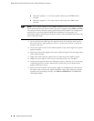
8. Remove the clear plastic cover protecting the terminal studs on the faceplate.
9. Remove the nuts and washers from the terminal studs.
10. Attach the lugs on the DC source power cables to the terminal studs, making
sure the cables are not touching or in the way of any router components (see
Figure 6 on page 10).
Replacing a DC Power Supply ■ 7
Replacing a DC Power Supply