


■
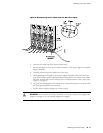
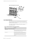
Attach the positive (+) DC source power cable lug to the RTN (return)
terminal.
■
Attach the negative (–) DC source power cable lug to the –48V (input)
terminal.
NOTE: The DC power supplies in slots PEM0 and PEM1 must be powered by dedicated
power feeds derived from feed A, and the DC power supplies in slots PEM2 and PEM3
must be powered by dedicated power feeds derived from feed B. This configuration
provides the commonly deployed A/B feed redundancy for the system. For
information about connecting to DC power sources, see the MX960 Ethernet Services
Router Hardware Guide.
11. Secure each power cable lug to the terminal studs, first with the split washer,
then with the nut. Apply between 23 lb-in. (2.6 Nm) and 25 lb-in. (2.8 Nm) of
torque to each nut.
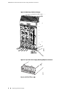
12. Loosen the captive screw on the cable restraint on the lower edge of the power
supply faceplate.
13. Route the positive and negative DC power cables through the left and right sides
of the cable restraint.
14. Tighten the cable restraint captive screw to hold the power cables in place.
15. Replace the clear plastic cover over the terminal studs on the faceplate.
16. Verify that the ground and power cabling are correct, that they are not touching
or blocking access to router components, and that they do not drape where
people could trip on them.
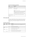
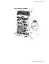
17.
Switch the circuit breaker on the power supply to the ON position and observe
the status LEDs on the power supply faceplate. If the power supply is correctly
installed and functioning normally, the PWR OK, BREAKER ON, and INPUT OK
LEDs light steadily.
8 ■ Replacing a DC Power Supply
MX960 Ethernet Services Router DC Power Supply Installation Instructions