11
ENGLISH
Controls and Features (cont.)
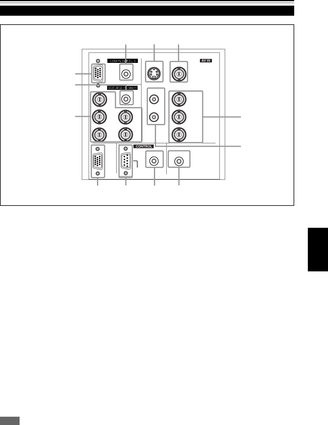
Connector Panel
1
Y/C (S video) input terminal (Mini DIN 4 pin)
Connect this terminal to the S video output terminal of a
video deck, etc.
2
VIDEO (composite video) input terminal (BNC)
Connect this terminal to the composite video output terminal
of a video deck, etc.
3
Y, PB/B-Y, PR/R-Y input terminals (BNC)
These are input terminals for component (Y, B-Y, R-Y)
signals or DTV-format (Y, P
B, PR) signals.
Device with component output terminals can be
connected.
* For details about DTV-format signals (480i, 480p, 720p,
1080i) compatible with this unit, refer to page 56.
4
AUDIO L/R (Audio • left/right) input terminals (pin jacks)
Of devices connected to the video input terminals, such
as a video deck, etc., the audio output terminals of the
device to be projected is connected to these terminals.
The input audio signal is reproduced by the speakers of
the projector. The signal is also output from the AUDIO
OUT terminal of the projector.
* When the input signal is stereo signal, connection should
be made to both L and R.
* Signals from a monaural device should be connected to
only L. That way, the projector’s speakers and the AUDIO
OUT terminal produce the same sound from both L and R.
Memo
To select the proper audio input for video input:
The video input terminals (AV IN input terminals) can be switched
with the projector’s or remote control’s VIDEO button. However, since
this projector has only single audio input terminal, reconnect audio
input in accordance with the AV device to be used.
5
AUDIO OUT (audio output) terminal (stereo mini jack)
Of input signals inputted to the projector, the audio signal
of the device being projected is output. Volume should be
adjusted using the VOL. (+/–) buttons on the remote control
or VOLUME on the setting menu. When a cable is
connected to this jack, no audio sound is produced from
the projector’s speakers.
6
REMOTE terminal (mini jack)
Connect an infrared remote control extension unit, etc. to
this jack.
* For details, consult your dealer.
7
RS-232C terminal (D-sub 9 pin)
This is a RS-232C interface-specified terminal. This
projector can be controlled by a computer connected
externally.
* For details, consult your dealer.
8
COMPUTER OUT (computer output) terminal (D-sub
3-row 15 pin)
The computer input signal projected on the screen is output.
A display unit can be used by connecting it to this terminal.
Y
PC
AUDIO
AUDIO
AUDIO
AUDIO OUT
REMOTE
Y/C VIDEO
Y
P
B
/B-Y
P
R
/R-Y
L
R
H/C
S
V
R
G
B
COMPUTER
OUT
RS-232C
w
1
2
q
p
9
8
7
6
5
3
4
M15U p.05-14 99.8.23, 9:06 PM11


