


14
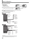
Menu Confi guration (cont.)
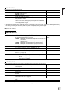
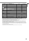
MARKER
*1*2
Settings for marker functions
2/2
Item To do Setting value
R-AREA MARKER
*3
Activate/deactivate the area marker and select the style of it.
*4
OFF, LINE, HALF, HALF+L, BLK. ,
BLK.+L
R-MARKER ASPECT
*3
Select the aspect ratio of the area marker. 4:3, 14:9, 13:9, 2.35:1, 1.85:1,
1.66:1
R-SAFETY MARKER Activate/deactivate the safety marker and select the style of it.
*4
OFF, LINE, HALF, HALF+L, BLK. ,
BLK.+L
R-SAFETY AREA Adjust the area of the safety marker. 80% – 100%
The area marker or the safety marker is displayed by using AREA MARKER or SAFETY MARKER button, or external control.
Select either non-“R-” items or “R-” items to activate by using external control. (☞
“External Control”
on page 18)
When a picture is displayed in 4:3 aspect ratio, the safety marker for the 4:3 area is displayed.
To display the safety marker for the area of a picture displayed in 16:9 aspect ratio, hide the area marker.
*1
Memorized for each input.
*2
Not displayed when the picture is displayed in the 1:1 mode and when “SD4:3 SIZE” setting in MAIN MENU is “H FULL” and the input signal
format is 4:3.
*3
Displayed only when picture is displayed in 16:9 aspect ratio.
*4
The setting values are the same as that of “AREA MARKER”. (☞ page 13).
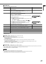
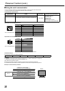
AUDIO SETTING
Settings for the audio output balance, EMBEDDED AUDIO signals and level meter
Item To do Setting value
BALANCE Adjust the balance between the right and left speakers. L5 – L1, 0, R1 – R5
AUDIO1 ASSIGN.
*1
Select the video input which the audio signal through AUDIO ASSIGN (IN 1)
terminal is assigned to.
SDI-1, SDI-2, DVI, VIDEO-1,
VIDEO-2
AUDIO2 ASSIGN.
*1
Select the video input which the audio signal through AUDIO ASSIGN (IN 2)
terminal is assigned to.
E.AUDIO GROUP
*2
Select the audio channel group of the EMBEDDED AUDIO signals.
The setting values and selectable audio channels of EMBEDDED AUDIO
signals are as follows.
(G means GROUP)
1G: channel(s) 1/2/3/4/1+2/3+4/1 – 4 (1G)
2G: channel(s) 5/6/7/8/5+6/7+8/5 – 8 (2G)
1-2G: channel(s) 1/2/3/4/5/6/7/8/1+2/3+4/5+6/7+8/1 – 4 (1G)/5 – 8 (2G)/
1 – 8 (1G+2G)
3G: channel(s) 9/10/11/12/9+10/11+12/9 – 12 (3G)
1-3G:
channel(s) 1/2/3/4/5/6/7/8/9/10/11/12/1+2/3+4/5+6/7+8/9+10/
11+12/1 – 4 (1G)/5 – 8 (2G)/9 – 12 (3G)/1 – 8 (1G+2G)/1 – 12 (1-3G)
1G, 2G, 1-2G, 3G, 1-3G
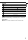
LEVEL METER
SETTING
*2
Adjust the level meter display for the EMBEDDED AUDIO signals.
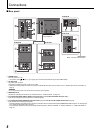
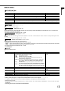
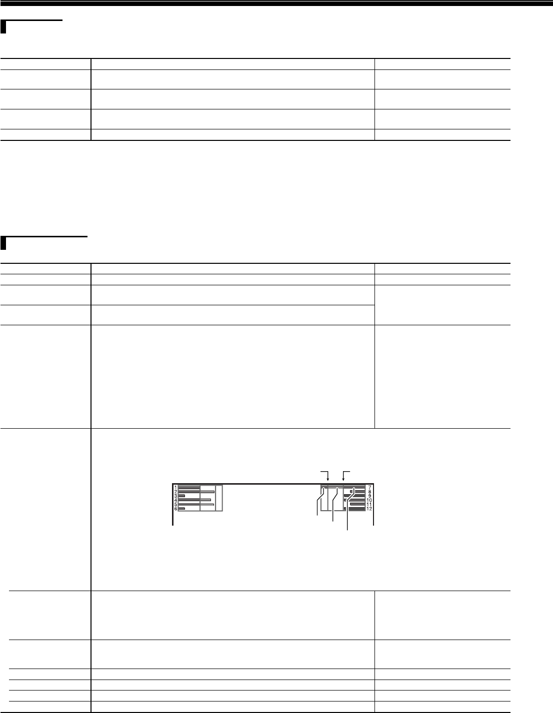
Example of the level meter display —Level meter position and audio channels
Ex.: When “LEVEL METER ch” is set to “LINE” and “BAR TYPE” is set to “3COLORS”
OVER LEVEL REFERENCE LEVEL
Yellow
Green
Red
The level meter with no audio signal input is displayed in white for “3COLORS”, and in gray for “W.100.”
You can select the position of the level meter display—top or bottom of the screen.
(☞ “POSITION” in “INFORMATION” on page 17)
When “PEAK HOLD” is set to “ON,” the maximum level meter value will remain displayed for a set period of time.
(At the time the signal input level reaches the highest value.)
•
•
•
– LEVEL METER ch Select how the audio channels are displayed on the level meter.
LINE: Displays the channels 1 – 6 at the left of the screen and 7 – 12 at
the right.
DIVIDE: Displays the odd channels at the left of the screen and the even
channels at the right.
OFF, LINE, DIVIDE
– BAR TYPE Select the color of the level meter display.
3COLORS: 3 colors to indicate variations in input levels.
W.100 : White
3COLORS, W.100
–
REFERENCE LEVEL
Select the standard input level indicated on the level meter. –20dB, –18dB
– OVER LEVEL Select the input level’s lower limit indicated in red for the “3COLORS” display. –10dB, –8dB, –6dB, –4dB, –2dB
– BAR BRIGHTNESS Select the brightness of the level meter. LOW, HIGH
– PEAK HOLD Activates/deactivates the peak hold function of the level meter. OFF, ON
*1
DT-R24L4D only
*2
Memorized for each input.
•
•
•
•