


19
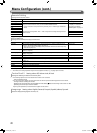
Function Key Setting
Specify the function assigned to the F1 button.
Function1 Specify the function assigned to the F1 button.
* See pages 13 to 22 for details of the functions assigned to Function 1.
- - -, Aperture,
I/P Mode,
Frame, Center Marker,
Level Meter Display,
Gamma, Color
Temperature,
CRC Error, Manual Aspect,
Time Code, 1:1, Dynamic
Function Display Select whether to display the status of the assigned function when you press the F1 button. Off, Mode-1, Mode-2
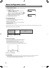
Off
Mode-1
Mode-2
:
:
:
No status display. Perform the registration function.
Display the status. Perform the registration function.
Display the status. Do not perform the registration function.
Perform the registration function when the status is displayed and the button is
pressed again.
●
To display the “Function Key Setting” menu, press the button when the menu is not displayed.
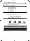
● About the operations of F1 button
Each time you press the button, the setting value for the assigned function changes in order.
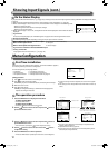
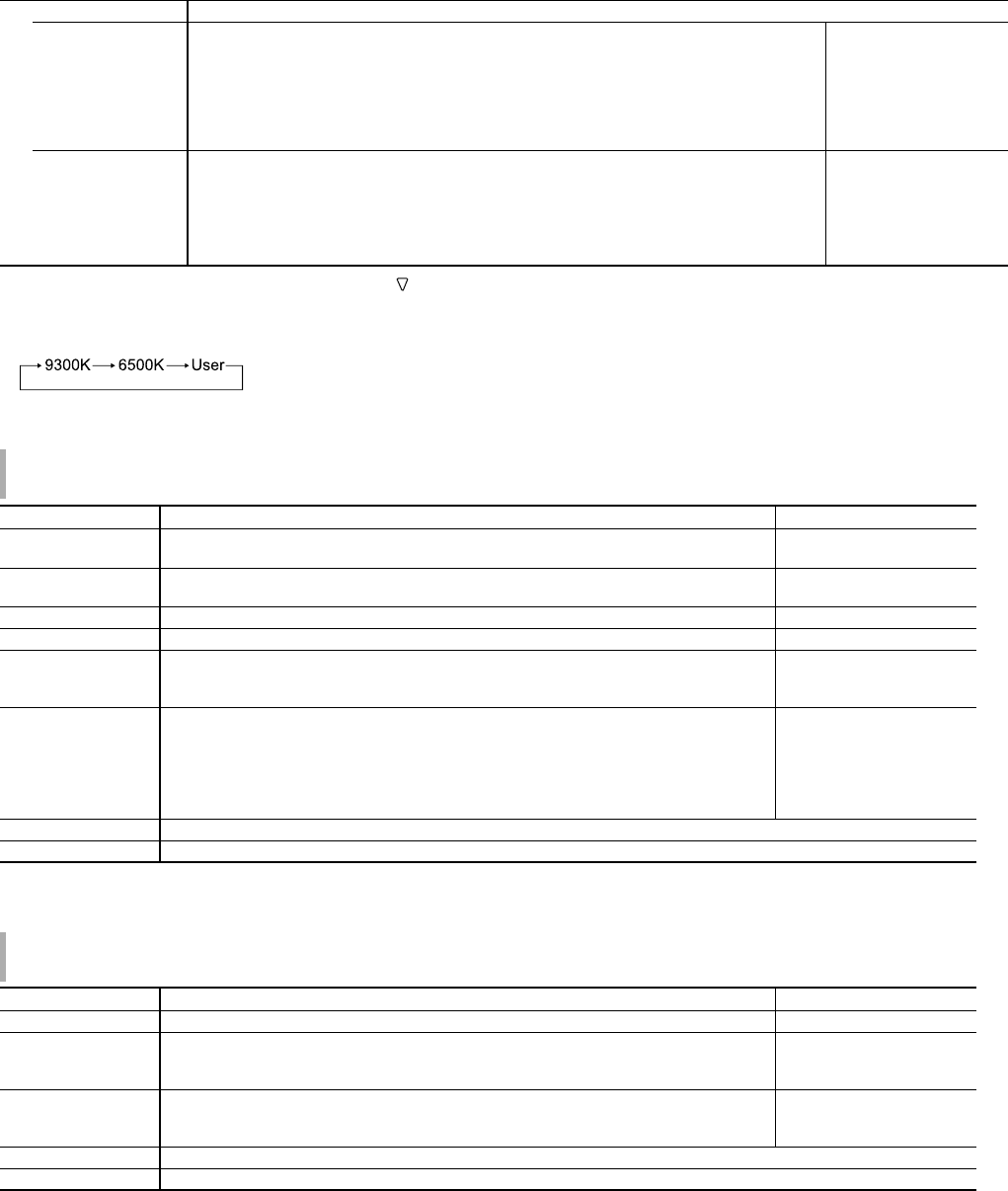
Ex: When “Color Temperature” is assigned
Each time you press the button, three setting values alternate.
Picture Sub Adjust
Configure the standard level of image adjustment.
Item To do Setting value
Contrast*
1
Adjust the standard level for the contrast adjusted with the CONTRAST knob on the front
panel.
–20 to +20
Bright*
1
Adjust the standard level for the brightness adjusted with the BRIGHT knob on the front
panel.
–20 to +20
Chroma*
1
Adjust the standard level for the chroma adjusted with the CHROMA knob on the front panel. –20 to +20
Phase*
1,
*
2
Adjust the standard level for the phase adjusted with the PHASE knob on the front panel. –20 to +20
NTSC Setup Select the set-up level of the input NTSC signal. 00 (compliant with 0 %
set-up signal), 7.5 (compliant
with 7.5 % set-up signal)
Component Level Select the level of the analog component signal (480i and 576i only). B75 (compliant with
BetacamVTR 7.5 % set-up
signal), B00 (compliant with
BetacamVTR 0 % set-up
signal), SMPTE (compliant
with M2VTR signals)
sub menu Display the sub menu which enables you to adjust the items in “Picture Sub Adjust” while viewing the actual picture.
reset Restore the default settings for all the items in “Picture Sub Adjust”.
*
1
Memorized for each input.
*
2
When “Component Phase” (☞ page 18) is set to “Disable,” “Phase” cannot be adjusted if no NTSC signal is input.
White Balance Setting
Display the color temperature, and adjusts the drive level and cutoff point of each color (R/G/B).
Item To do Setting value
Color Temperature Select the color temperature. (Cannot be set/changed) 9300K, 6500K, User
R Drive *
1
G Drive
B Drive
Adjust the drive level of each color (red, green, and blue).
● The maximum (Max) and minimum (Min) values vary depending on the input signal or
other settings.
Min – 000 – Max
(in 1024 grades)
R Cut Off *
1
G Cut Off
B Cut Off
Adjust the cutoff point of each color (red, green, and blue).
● The maximum (Max) and minimum (Min) values vary depending on the input signal or
other settings.
Min – 000 – Max
(in 1024 grades)
sub menu Display the sub menu which enables you to adjust the items in “White Balance Setting” while viewing the actual picture.
reset Restore the default settings for all the items in “White Balance Setting”.
*
1
Memorized for each color temperature.
DT-V9L5_EN_1.indb 19DT-V9L5_EN_1.indb 19 10/10/2012 5:18:53 PM10/10/2012 5:18:53 PM