


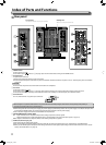
11
Volume Adjustment/Audio Channel Selection
Volume Adjustment
1 When no menu screen is not displayed, press (volume adjustment button)
For SDI input the “Volume/Embedded Audio” screen appears. For any input other than SDI the “Volume”
screen appears.
2 Press to move the cursor to “Volume”
(This step is skipped when the ”Volume/Embedded Audio” screen is not displayed.)
3 Press
to adjust the volume
4 Press the MENU button to finish
(The “Volume” screen disappears automatically if no operations are made for 5 seconds.)
Audio Channel Selection
Select the audio channel output from the Speaker (monaural) and AUDIO (MONITOR OUT) (OUT1(L)/OUT2(R))
terminals when an EMBEDDED AUDIO signal is input during SDI input.
● It is necessary to set the audio channel group in advance. (☞ ”Embedded Audio Group” of “Audio Setting”
on page 16)
● Store the setting for each input of SDI 1 and SDI 2.
● Set “SDI-1 Select” or “SDI-2 Select” to “Auto” or “Digital”.
1 When the menu is not displayed, use the buttons
The “Volume/Embedded Audio” screen appears.
● The “Volume/Embedded Audio” screen disappears automatically is no operations are made for about 30 seconds.
2 Use the
buttons to select the left and right channels (L ch/R ch)
3 Use the buttons to select the audio channel
● Each time you press a button the audio channel changes according to the “Embedded Audio Group” setting. (☞ page 16)
4 Press the MENU button
● The “Volume/Embedded Audio” screen disappears.
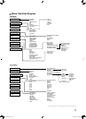
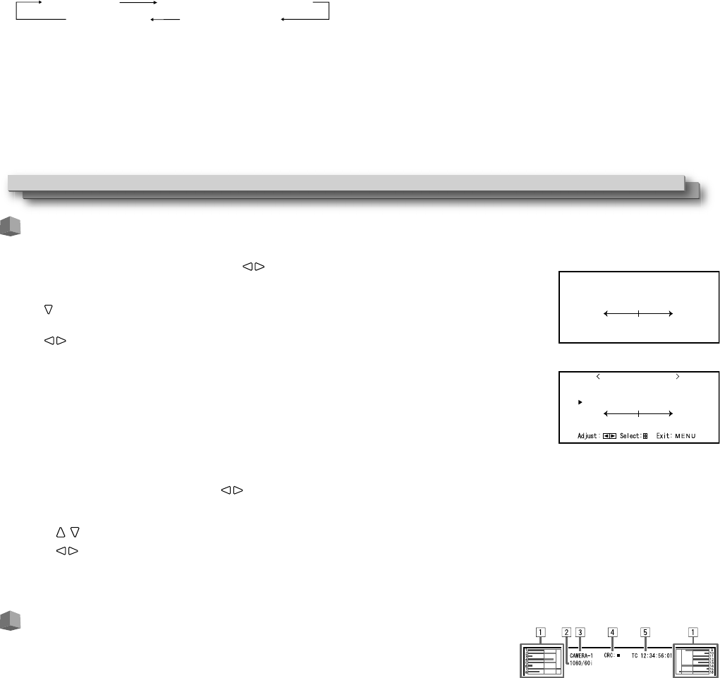
On the Information Display
The monitor displays the information below.
● You can set whether the information for each setting is displayed/hidden in the MENU.
1 Audio level meter
● You can check the conditions of the EMBEDDED AUDIO signals when “Level Meter Display” is set to “Horizontal” or “Vertical.” (☞ “Audio
Setting” on page 16)
● Not displayed when “Level Meter Display” is set to “Off.”
2 Signal format
● Displayed when “Status Display” is set to “On” or “Auto.” (☞ “Information” on page 20)
● For the contents displayed, see “Available signals” on page 30 and “On the signal format” on page 12.
3 Source name assigned in “Character Setting”
● Displayed when “Source ID” is set to “On” or “Auto.” (☞ “Information” on page 20)
● Displayed in large letters when “Status Display” is set to “Off” or “Auto.”
4 CRC error indication
● Displayed when “CRC Error” is set to “On.” (☞ “Information” on page 20)
● A red square is displayed when an error occurs.
5 Time code
● When the input signal includes no time code, “TC – –:– –:– –:– –” is displayed. (☞ “Information” on page 20)
y SCOPE button/lamp
Displays/hides the indication of the wave form monitor and vectorscope (☞ “Scope Setting” on page 17).
● Each time you press this button, the window changes in the following order.
Wave form monitor
Vectorscope
No display
u DC lamp
When the DC power voltage is being lowered due to the battery consumption, the lamp changes to orange from green. When the voltage
becomes lower than a certain level, the monitor automatically turns off and the lamp turns to red.
● Make sure to turn off the POWER switch and DC switch on the rear panel before replacing the battery.
● The length of time that the lamp lights in orange differs depending on the type of battery or the battery condition. It is recommended to
replace the battery when the lamp turns to orange.
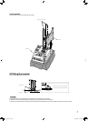
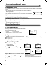
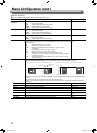
9ROXPH
Volume screen
9ROXPH(PEHGGHG$XGLR
*
(PEHGGHG$XGLR/FK
(PEHGGHG$XGLR5FK
9ROXPH
Volume/Embedded Audio screen
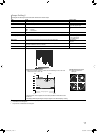
Showing Input Signals
Histogram
DT-V9L5_EN_1.indb 11DT-V9L5_EN_1.indb 11 10/10/2012 5:18:46 PM10/10/2012 5:18:46 PM