


16
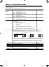
Menu Configuration (cont.)
Audio Setting
Settings for EMBEDDED AUDIO signals and audio level meter signal.
Item To do Setting value
SDI-1 Select
SDI-2 Select
Select the input through which audio is output. Off, Auto, Digital, Analog
Off
Auto
Digital
Analog
:
:
:
:
Does not output audio.
Output digital audio prior to analog audio.
Output audio from the SDI terminal.
Output audio from the AUDIO IN terminal.
HDMI Select Select the input through which audio is output. Off, Digital, Analog
Off
Digital
Analog
:
:
:
Does not output audio.
Output audio from the HDMI terminal.
Output audio from the AUDIO IN terminal.
Video/Component Select Select the input through which audio is output. Off, Analog
Off
Analog
:
:
Does not output audio.
Output audio from the AUDIO IN terminal.
Embedded Audio Group*
1
Select the audio channel group of the EMBEDDED AUDIO signals.
The setting values and selectable audio channels of EMBEDDED AUDIO signals are as follows.
(G means GROUP)
1G, 2G, 1-2G ,3G, 4G, 1-4G,
3-4G
1G
2G
1-2G
3G
4G
1-4G
3-4G
:
:
:
:
:
:
:
channel(s) 1/2/3/4/1+2/3+4/1 – 4 (1G)
channel(s) 5/6/7/8/5+6/7+8/5 – 8 (2G)
channel(s) 1/2/3/4/5/6/7/8/1+2/3+4/5+6/7+8/1 – 4 (1G)/5 – 8 (2G)/
1 – 8 (1G+2G)
channel(s) 9/10/11/12/9+10/11+12/9 – 12 (3G)
channel(s) 13/14/15/16/13+14/15+16/
13 - 16(4G)
channel(s) 1/2/3/4/5/6/7/8/9/10/11/12/13/14/15/16/1+2/3+4/
5+6/7+8/9+10/11+12/13+14/15+16/1–4(1G)/5–8(2G)/9–12(3G)/13-16(4G)/
1–8(1G+2G)/1-16(1-4G)
channel(s) 9/10/11/12/13/14/15/16/9+10/11+12/
13+14/15+16/
9 –12 (3G)/
13-16(4G)/9-16(3-4G)
Level Meter Setting*
1
Specify the audio level meter display for EMBEDDED AUDIO signal.
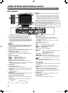
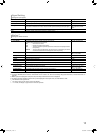
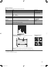
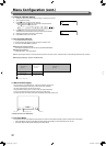
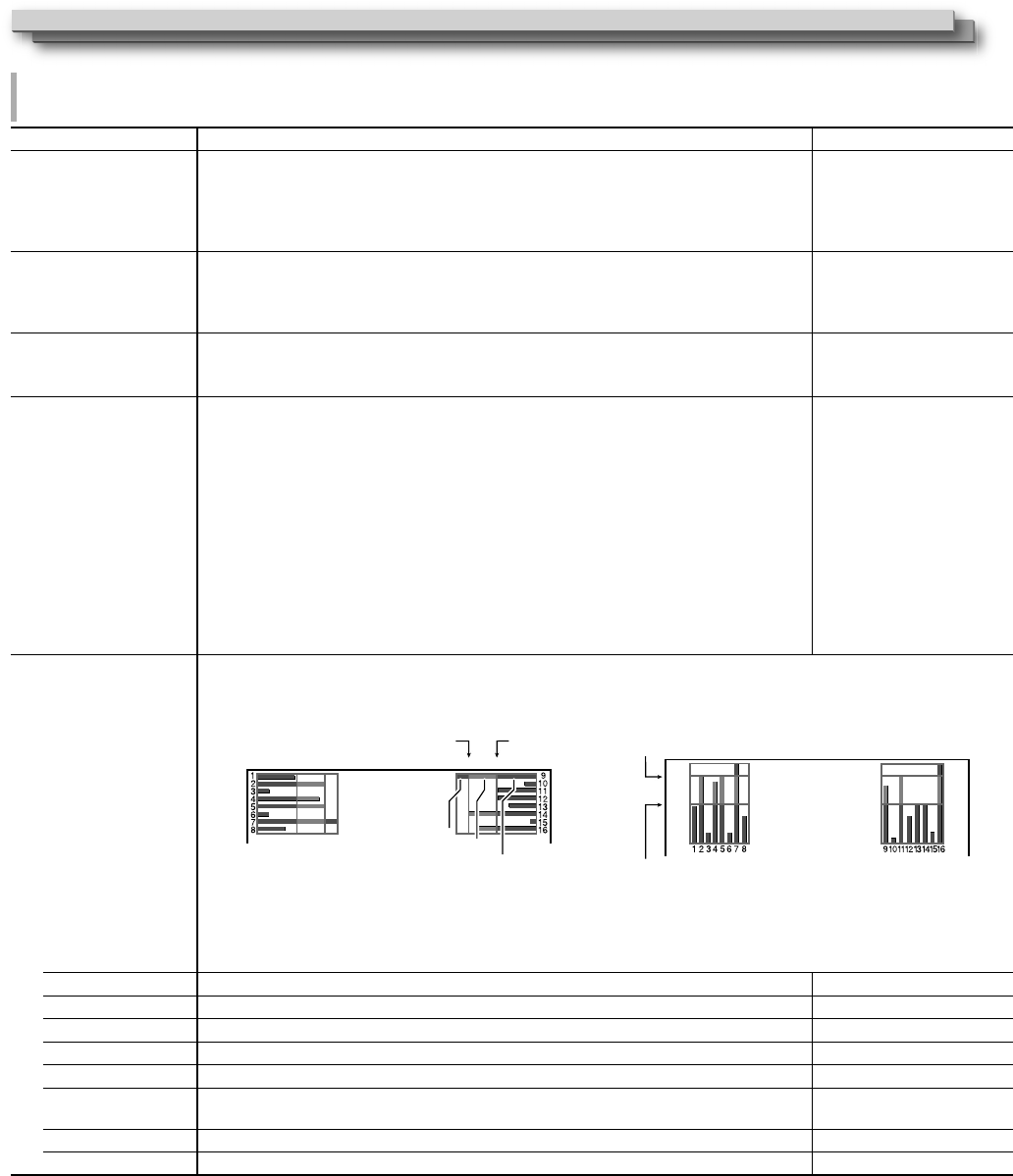
Example of audio level meter display - Connection between the level meter position and channel
Ex: When “Horizontal” is selected for “Level Meter Display”: Ex: When “Vertical” is selected for “Level Meter Display”:
-10dB -20dB-20dB -10dB
-20dB
-10dB
-20dB
-10dB
• The number of audio channels displayed on the level meter varies depending on the setting value of “Embedded Audio
Group”.
• The audio level meter can be displayed at the top or bottom of the screen.
• When “On” is selected for “Peak Hold”, the maximum value is retained a certain period when the signal level becomes
maximum.
Level Meter Display Select the status of the level meter (display vertically, horizontally, or not displayed). Off, Vertical, Horizontal
Channel Arrange
Select how the audio channels are displayed on the level meter.
Line, Divide
Position Adjust the vertical level meter position. Upper, Lower
Meter Type Specify the design of the level meter. Bar, Block
Reference Level Select the standard input level indicated on the level meter. –20dB, –18dB
Over Level Select the input level’s lower limit indicated in red. –10dB, –8dB, –6dB, –4dB,
–2dB
Transparent Adjust the transparency of the level meter display against the image. Off, Background, All
Peak Hold Activates/deactivates the peak hold function of the level meter. Off, On
*
1
Memorized for each input.
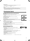
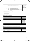
Green
REFERENCE
LEVEL
OVER LEVEL
Red
Yellow
OVER LEVEL
REFERENCE LEVEL
DT-V9L5_EN_1.indb 16DT-V9L5_EN_1.indb 16 10/10/2012 5:18:51 PM10/10/2012 5:18:51 PM