


KD-MSW4x2 Operating Instructions
Page 20
KD-MSW4x2 Operating Instructions
Page 21
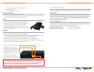
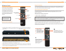
Control Connections
Decide how the KD-MSW4x2 will be controlled. If using an IR (Infrared) Extender, the wired IR,
or an external Control System (via the RS-232 port on the KD-MSW4x2), make the appropriate
connections now.
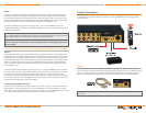
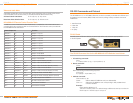
RS-232
The KD-MSW4x2 HDTV Matrix Switcher is compatible with all Control Systems. Use the D-sub
9-pin connecter on the rear panel and an appropriate cable to attach the unit to an external Control
System. An RS-232 cable is not supplied* with the base KD-MSW4x2 unit. Carefully insert your
own RS-232 cable (9-pin) to the back of the unit, and to an appropriate PC or Control System.
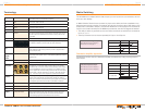
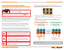
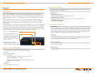
RGBHV
If the set-top receiver of choice employs RGBHV outputs, a 15-pin “breakout” adapter cable may
needed to implement the interface. In this instance connect the red, green and blue connectors
from this adapter cable to the red, green and blue connectors, again on any one of the four Input
Ports of the KD-MSW4x2 unit. Connect the black and yellow wires from the breakout cable to the
white (H) and red (V) connectors of the same Input Port of the KD-MSW4x2 unit.
Connect the RGBHV video signals from Output Ports 1 or 2 on the KD-MSW4x2 unit to the
corresponding RGBHV video jacks on the desired display. A second 15-pin breakout cable may be
required for certain sets.
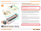
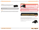
Lower-quality S-Video (two-wire) or Composite Video (CVBS) Source Equipment
S-Video
For S-Video applications, a “breakout” adapter cable is required to connect a source device to the
KD-MSW4x2 unit. This cable is equipped with an S-Video (DIN) plug at one end and a pair of RCA
plugs at the other connected to white and yellow conductors. Connect the white (Y) conductor to
the green RCA connector of the selected Input Port, and connect the yellow (C) conductor to either
the blue or red RCA connector in the same input field. Connect the white and red analog stereo
audio connectors of the source device to the white and red connectors in the same Input Port of
the KD-MSW4x2 unit.
Connect the green RCA connector from Output Ports 1 or 2 on the KD-MSW4x2 unit to the white
(Y) conductor of a second S-video adapter cable. Connect the blue or red connector to the yellow
(C) conductor. Plug the other end of the adapter cable into the TV or monitor's S-video input.
Connect the white and red analog stereo audio cable connectors to the white and red connectors
of the same Output Port on the KD-MSW4x2 unit. Connect the other end of the audio cable pair to
the white and red analog audio input of the display.
Composite Video (CVBS) Connection
Connect the Composite Video connector (yellow) from a VCR or other source device to the green
RCA connector in the selected Input Port on the KD-MSW4x2 unit. Connect another composite
video cable from the green RCA connector from Output Ports 1 or 2 on the KD-MSW4x2 unit to the
TV or video monitor. Follow the instructions above for connecting analog audio.
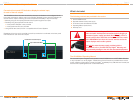
It is not possible to use analog audio switching when in RGB video applications because the H&V
sync signals required for the RGB format occupy the port connectors typically used for the audio
signals. Digital PCM may be used for this application, as described above.
This same connection procedure described above applies to any other peripheral device
that one may wish to interface with a desired display medium, including DVD players and
game consoles.
If applicable, Key Digital
™
‚ Fat Boy KD-MSW4x2 expansion units come preconfigured from the factory with their own
RS-232 cable