


KD-MSW4x2 Operating Instructions
Page 14
KD-MSW4x2 Operating Instructions
Page 15
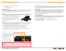
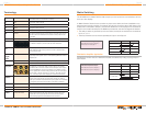
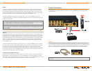
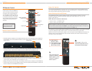
Each connector can accommodate various signals, on a shared basis:
Red Connector: Pr/R
Pr label is for component video
R label is for the red channel for RGBHV video
Green Connector: Y/G
Y label is for component video
G label is for the green channel for RGBHV video
Blue Connector: Pb/B
Pb label is for component video
B label is for the blue channel for RGBHV video
White Connector: L/H
L label is for the left analog stereo audio channel
H label is for the horizontal sync for RGBHV video
Red Connector: R/V (Right analog stereo audio, or vertical sync for RGBHV video)
R label is for the right analog stereo audio channel
V label is for the vertical sync for RGBHV video
Black Connector: PCM
For PCM digital coax audio
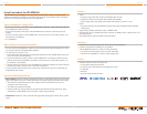
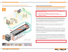
The following connectors are also provided on the rear panel:
RS-232 Connector
IR Extender sensor
Wired IR serial port
External power supply connector
›
➔
»
»
➔
»
»
➔
»
»
➔
»
»
➔
»
»
➔
»
›
➔
➔
➔
➔
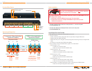
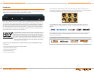
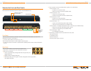
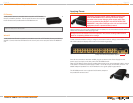
Examine the Front and Rear Panels
Become familiar with the front and rear panels of the KD-MSW4x2 unit.
Front Panel
The front panel contains the pushbutton selection switches and associated input select LED
indicators for Output 1 and Output 2:
For each output, select source Input 1, 2, 3, or 4
The IR remote control sensor is also located on the front panel:
A clear line-of-site to the sensor is required when operating the IR remote control provided with
the unit
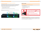
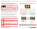
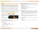
Rear Panel
The rear panel contains 4 Input Ports and 2 Output Ports:
Each Port is comprised of 6 color-coded RCA connectors
Each Port can support:
YPbPr component video, analog stereo left and right audio, and
digital PCM audio
RGBHV video and digital PCM audio
RGB video with sync on the green channel, analog stereo left and right audio,
and digital PCM audio
›
›
›
›
➔
➔
➔
Inputs
Outputs
Power Supply
Wired IR
IR Extender
RS-232
1 2 1 23 4
Pushbutton to Select Input
Input Selected LEDs
IR Remote Sensor