


xiv
NovaJet 500/630/700 Series Service Manual
List of Illustrations
Figure Page
Chapter 1 General Description
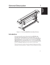
1-1. NovaJet 500/630/700 Series Inkjet Printers ..................................................... 1-1
Chapter 2 Theory of Operation
2-1. General Block Diagram ................................................................................... 2-2
2-2. Paper (Media) Axis Drive .................................................................................2-3
2-3. Carriage Axis Drive.......................................................................................... 2-4
2-4. Power Feed and Take-Up System ...................................................................2-5
2-5. Main Printed Wiring Assembly ........................................................................2-6
2-6. Gate Array ......................................................................................................2-7
2-7. Stepper Motor Controller ............................................................................... 2-10
2-8. Servo Motor Controller ................................................................................... 2-12
2-9. Quadrature Signal Generation ....................................................................... 2-13
2-10. Interface Circuits ........................................................................................... 2-14
2-11. Carriage Assembly Circuits ........................................................................... 2-15
2-12. Main Menu .................................................................................................... 2-16
Chapter 3 Maintenance
3-1. Encoder Strip Cleaning ...................................................................................3-5
3-2. Cartridge Dimple Region.................................................................................. 3-5
3-3. Flex Cable Contacts .......................................................................................3-6
3-4. MPWA Connection Locations ......................................................................... 3-9
3-5. Carriage PWA Connection Locations ............................................................ 3-10
3-6. Ribbon Connector Locking Mechanism ......................................................... 3-11
3-7. Servo Motor................................................................................................... 3-12
3-8. Stepper Motor ............................................................................................... 3-13
3-9. Power Feed and Take-Up Motor .................................................................... 3-14
3-10. Examples of Banding ....................................................................................3-15
3-11. Dial Gauge Micrometer Assembly ................................................................. 3-19
3-12. Measurement Positions for Slide Shaft.......................................................... 3-20
3-13. Slide Shaft Profile Adjustment ....................................................................... 3-21
3-14. Carrier Head Height Tolerance ....................................................................... 3-22
3-15. Setting Up Tools from Height Gauge Kit ........................................................ 3-22
3-16. Zeroing the Micrometer Gauge ...................................................................... 3-23