7
n Names of Parts and Functions
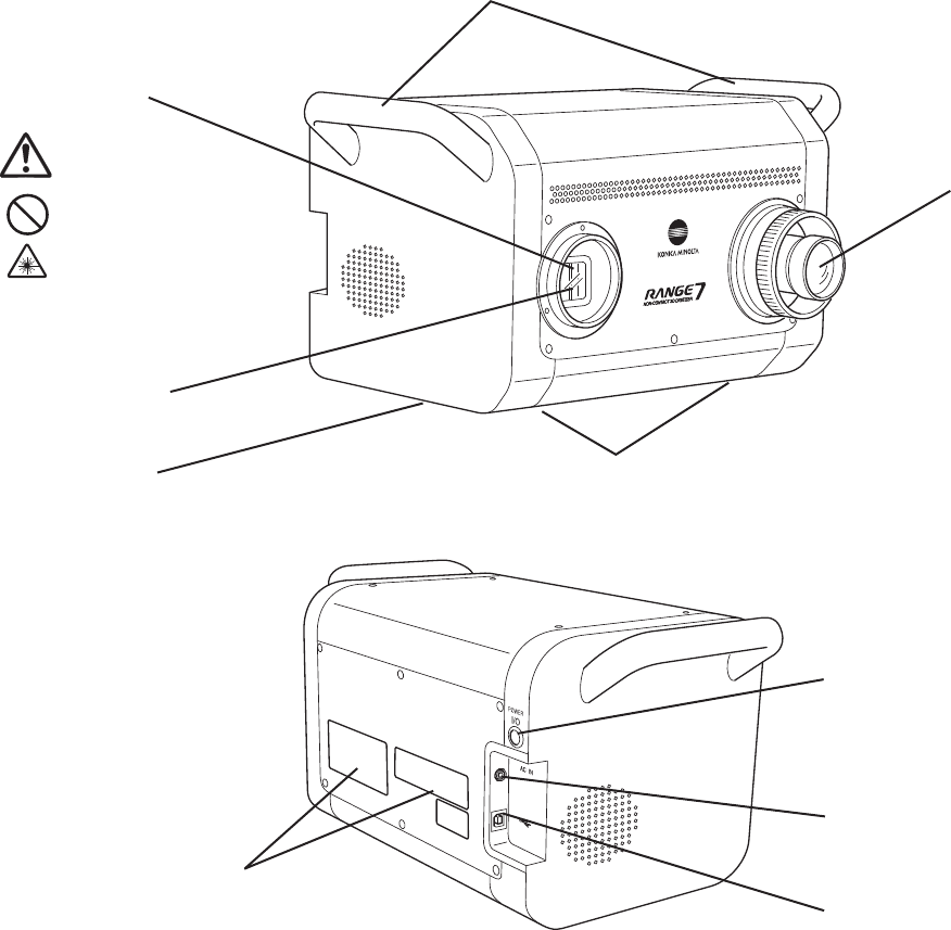
1) Carrying handle UsedtoliftorcarrytheRANGE7/5.(BesuretoholdtheRANGE7/5bodywithbothhands.)
2) Light-receiving lens Exchangethelight-receivinglensforanoptimumlens(TeleorWidelens),dependingon
themeasuringtargetsizeandmeasuringdistance.
3) Laser-emitting window Alaserbeamisemittedtoameasuringtargetfromthiswindow.(Donotstaredirectlyinto
thelaserbeam.)
4) Lens shutter Whenthepowerisswitchedoff,thisshutterclosestoprotectthelaseremittingwindow.
5) Rubber sole FourrubbersolesareattachedatthebottomoftheRANGE7/5.ToinstalltheRANGE7/5
directlyonarmtable,usetheseparts.Also,usethecalibrationchartsetduringeld
calibration(understandardaccessories);orwhenmountingtheRANGE7/5tothetripod
set,ormeasuringstandset(underoptionalaccessories),usethesepartstosetthe
RANGE7/5inplace.
6) Platform mounting screw hole ScrewholesforfasteningtheRANGE7/5tothemeasuringstandplatformortripod
platform(underoptionalaccessories).
7) Power switch TurnsON/OFFtheRANGE7/5powersupply.
8) AC adaptor terminal ConnecttheRANGE7/5ACadaptorplugtothisterminal.
9) USB port WhenconnectingtheRANGE7/5toaPC,connecttheUSBcable(standardaccessory)
Type B plug.
3)Laser-emittingWindow
4)Lasershutter
5)Rubbersole
7)Powerswitch
8)ACadapterterminal
6)Platformmountingscrewhole
WARNING
Alaserbeamisemitted
from this port.
Do not stare directly into
the laser beam.
1)Carryinghandle
2)Light-ReceivingLens
9)USBport(TypeB)
LaserLabelIndication(page3)


