


Installation Installation
2 - 2
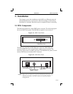
Four or Þve LEDs are located on the top of the unit. Table 2-1 explains their
functions.
NOTE:
Although a red LED during boot mode usually signals an error,
red LED patterns are part of the normal operation of the MSS
and are not necessarily indicative of errors or dangerous
operation.
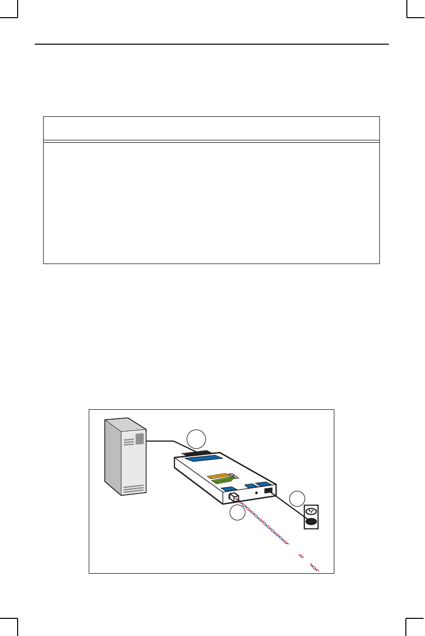
2.2 Installation
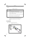
Figure 2-3 shows an example hardware layout.
Figure 2-3:
MSS Network Layout
Table 2-1:
MSS LEDs
LED Function
Power Glows green when power is supplied to the Server
Link Glows green while the Server is connected properly to a 10BASE-T or
100BASE-T (MSS100 only) Ethernet network (The Link LED does not
function for 10BASE2 connections)
100 MSS100 only: glows green to indicate a 100BASE-T Ethernet connection
OK Blinks yellow, green, or red to indicate Server activity.
Serial Blinks yellow, green, or red to indicate serial activity.
4
3
MSS
2
10BASE-T
Ethernet
Serial
Device